
Electric signal counting photoelectric direct reading device for remote transmission instrument

A photoelectric direct reading and electrical signal technology, applied in the direction of measuring devices, instruments, conversion sensor output, etc., can solve the problems of poor anti-interference ability, large number of components, low production cost, etc., achieve small refraction influence, high measurement accuracy, The effect of low production cost

Inactive Publication Date: 2015-09-30
沈阳蓝海灵豚投资有限公司
View PDF11 Cites 0 Cited by
  • Summary
  • Abstract
  • Description
  • Claims
  • Application Information

AI Technical Summary

Problems solved by technology

[0006] The purpose of the present invention is to provide a photoelectric direct reading device for counting electrical signals for remote meters, which solves the problems of the existing photoelectric direct reading device, such as large number of components, poor anti-interference ability, high bit error rate, etc., and its structural design is reasonable , high measurement accuracy, low bit error rate, strong anti-interference ability, suitable for various environments, suitable for batch processing and production, and low production cost

Method used


Image

  • Electric signal counting photoelectric direct reading device for remote transmission instrument
  • Electric signal counting photoelectric direct reading device for remote transmission instrument
  • Electric signal counting photoelectric direct reading device for remote transmission instrument

Examples


Embodiment Construction

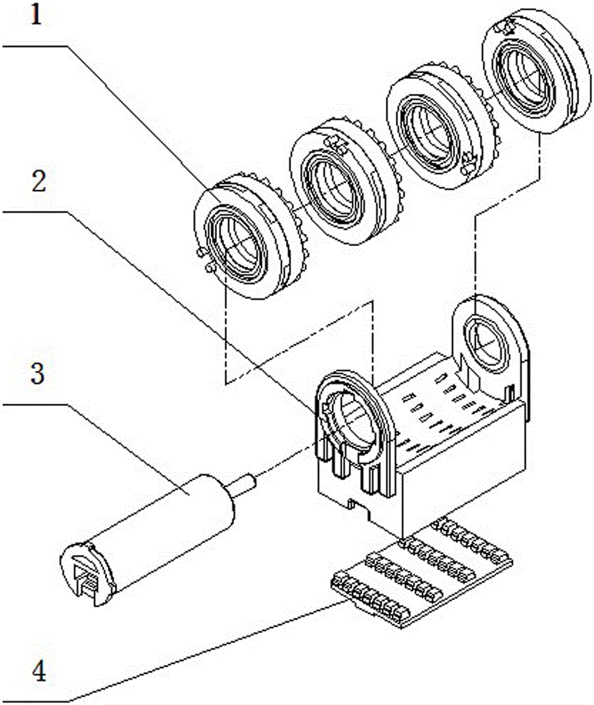
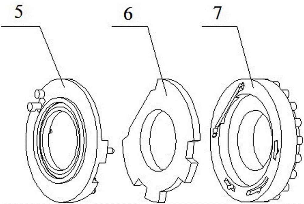
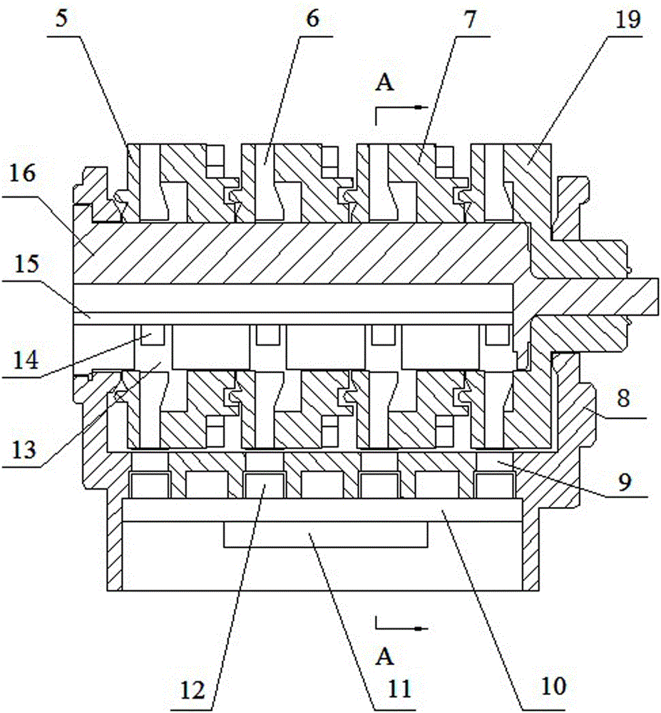
[0027] according to Figure 1-13The specific structure of the present invention will be described in detail. The photoelectric direct reading device for counting electrical signals for remote meters includes a light guide assembly 2 with a decoder 4, and a multi-digit code wheel 1 assembled on the light guide assembly 2 through a light-emitting shaft assembly 3. components such as groups. Wherein in the encoding character wheel group, except that the right shading wheel body of the right encoding character wheel adopts the transmission shading wheel body 19, all the other encoding character wheels 1 are composed of the left shading wheel body 5, the right shading wheel body 7 and the two wheel bodies. The transparent wheel body 6 between them is assembled into an integral structure, or the transparent wheel body 6 is placed in the middle of the left light-shielding wheel body 5 and the right light-shielding wheel body 7 by secondary injection molding. The left shading wheel ...


PUM


Abstract

An electric signal counting photoelectric direct-reading device for remote transmission instruments solves the problems of large quantity of elements, poor antijamming capability and large error rate and the like of the existing photoelectric direct-reading device. The device comprises a light guide assembly with a decoder and a coded word wheel group assembled on the light guide assembly by a lighting shaft assembly; the technical key points are that each coded word wheel in the coded word wheel group is formed by integrally splicing a left light shielding wheel body, a right light shielding wheel body and a transparent wheel body; a light transmitting wheel disk groove of the transparent wheel body is matched and spliced with laterally arranged bosses of the left and right light shielding wheel bodies; a light receiving tube in a light guide hole of the light guide assembly converts an optical signal sent from a lighting tube of the lighting shaft assembly into an electric signal to be decoded by a decoding chip, so a radial light ray transmission path starting from the lighting shaft assembly, to the coded word wheels, the light guide assembly, and the decoder in sequence is formed. The electric signal counting photoelectric direct-reading device for the remote transmission instruments is reasonable in structural design, high in measuring precision, low in error rate, strong in antijamming capability, suitable for various environments and machining and production in batch and low in production cost.

Description

technical field [0001] The invention relates to a counting mechanism for expressing counting results in the form of electrical signals applied to remote metering water meters, electric meters, gas meters and other instruments of photoelectric devices, in particular to a photoelectric direct reading device for counting electrical signals for remote meters. Background technique [0002] At present, with the rapid development of electronic digital technology, the traditional mechanical structure of meters such as water meters, electricity meters, and gas meters, their decimal mechanical rotary counters are gradually being applied to the coding wheel photoelectricity of remote meters by mechatronics. Instead of direct-reading devices, the existing photoelectric direct-reading devices for meters at home and abroad are mainly divided into the following types according to their codes and optical path structures: axial transmission type, radial reflection type and radial transmission...

Claims


Application Information

Patent Timeline
Patent Type & Authority Patents(China)
IPC IPC(8): G01D5/347
Inventor 杨子昂
Owner 沈阳蓝海灵豚投资有限公司
Learn More