
Time-frequency slice analysis-based rolling bearing fault diagnosis method

A rolling bearing and time-frequency slicing technology, which is applied in mechanical bearing testing and other directions, can solve problems such as excessive computing time, inability to effectively extract damage characteristic frequencies, and long signal envelope time, and achieve the effect of reducing misjudgment

Inactive Publication Date: 2014-01-08
CHANGAN UNIV
View PDF4 Cites 42 Cited by
  • Summary
  • Abstract
  • Description
  • Claims
  • Application Information

AI Technical Summary

Problems solved by technology

In addition, the method of wavelet packet decomposition can represent non-stationary characteristics more effectively, but its decomposition effect is closely related to the selection of wavelet basis functions and the number of decomposition layers, and the selection of wavelet basis functions affects the analysis results
[0007] (3) The optimization method is used to extract the envelope. In some cases, there will be local extremum or no extremum points, which will affect the effectiveness of envelope extraction; time
For optimal frequency band selection, the larger the bandwidth of the original signal, the greater the room for selection, and the expanded bandwidth, but it will introduce a large amount of data to be processed, and more computing time is required to select the optimal frequency band.
[0009] (5) The vibration signal of rolling bearing is a comprehensive response of internal and external excitation sources applied to bearings, bearing housings, casings, connected mechanisms, etc., which contains vibration responses of multiple natural frequencies. When multiple damages occur at the same time, They excite these natural frequencies to produce vibration responses that are not uniform. If a frequency band is selected for analysis, it is not possible to effectively extract all the characteristic frequencies of the damage.

Method used


Image

  • Time-frequency slice analysis-based rolling bearing fault diagnosis method
  • Time-frequency slice analysis-based rolling bearing fault diagnosis method
  • Time-frequency slice analysis-based rolling bearing fault diagnosis method

Examples


specific Embodiment

[0045] 1. Collect the vibration signal of the rolling bearing, and remove the DC component in the vibration signal of the rolling bearing. The vibration signal of the rolling bearing is collected by the acceleration sensor, and the acceleration sensor is installed on the support or bearing seat of the rolling bearing;

[0046] Let the vibration signal s(t) of the rolling bearing be f s Sampling for the sampling frequency to obtain a length N signal sequence S={s i ,i=1~N}, it corresponds to the time interval [0,...,t j ,...,t N-1 ], where t j =j / f s , j=0~N-1;

[0047] The formula for removing the DC component in the vibration signal is:

[0048] x i = s i - S ‾ , i = 1 ~ N - - - ( 1 )

[0049] in, is t...


PUM


Abstract

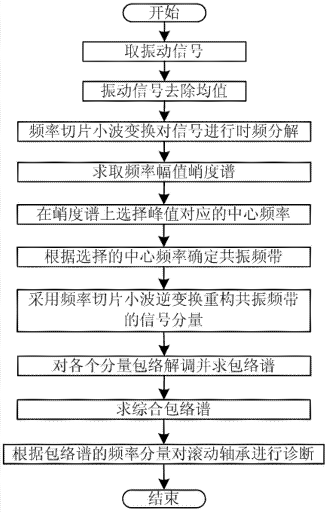
The invention discloses a time-frequency slice analysis-based rolling bearing fault diagnosis method. The method comprises the following steps: performing time-frequency decomposition on a vibration signal of a rolling bearing by using frequency slice wavelet transform to obtain a time-frequency energy distribution matrix of the vibration signal; then defining a kurtosis index, i.e., frequency amplitude kurtosis, on the basis of the time-frequency energy distribution matrix; solving the amplitude kurtosis corresponding to each frequency in sequence to form a frequency amplitude kurtosis spectrum of the vibration signal in a time-frequency plane; selecting a plurality of resonant frequency bands on the amplitude kurtosis spectrum; separating resonant frequency band signal components by using frequency slice inverse wavelet transform through a reconstruction method; extracting an envelope component of each resonant frequency band and performing rule processing by using a demodulation analysis method respectively; solving the comprehensive envelope spectrum of the envelope components on the basis; finally recognizing the damage characteristic frequency of the rolling bearing by using the comprehensive envelope spectrum to realize fault diagnosis of the rolling bearing.

Description

technical field [0001] The invention belongs to the technical field of rolling bearing damage fault diagnosis, and in particular relates to a rolling bearing fault diagnosis method based on time-frequency slice analysis. Background technique [0002] Rolling bearings are one of the most commonly used parts in mechanical equipment, and its damage is also one of the reasons for equipment failure and shutdown. Therefore, great attention is paid to its inspection and monitoring during the working process of the equipment. The use of vibration signal online monitoring is a large-scale equipment. one of the methods. [0003] Rolling bearings are composed of outer rings, inner rings, rolling elements, and cages. When a component is damaged during operation, its eigenfrequency is known. Therefore, the damaged component can be determined by calculating the eigenfrequency. The characteristic frequency of damage is related to the rolling bearing structure and its rotation frequency. ...

Claims


Application Information

Patent Timeline
IPC IPC(8): G01M13/04
Inventor 段晨东高鹏张彦宁徐先峰高强
Owner CHANGAN UNIV
Learn More