Shift register unit, GOA (gate driver on array) circuit, array substrate and display device

A shift register and charging module technology, applied in static memory, digital memory information, instruments, etc., can solve the problems that it is difficult to meet the requirements of narrow borders of array substrates, and the array substrates occupy a large area, so as to reduce the number and meet the requirements of narrow borders demand, the effect of reducing the area

Active Publication Date: 2014-01-08
HEFEI BOE OPTOELECTRONICS TECH +1
View PDF5 Cites 38 Cited by
  • Summary
  • Abstract
  • Description
  • Claims
  • Application Information

AI Technical Summary

Problems solved by technology

In the process of implementing the present invention, the inventors found that the existing GOA circuit still occupies a relati

Method used


Image

  • Shift register unit, GOA (gate driver on array) circuit, array substrate and display device
  • Shift register unit, GOA (gate driver on array) circuit, array substrate and display device
  • Shift register unit, GOA (gate driver on array) circuit, array substrate and display device

Examples


Embodiment 1

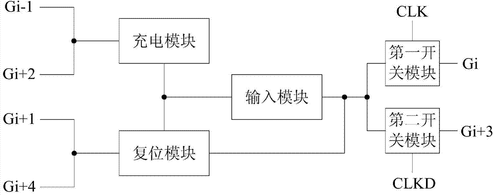
[0051] like figure 1 As shown, the shift register unit includes an input module, a charging module, a reset module, a first switch module and a second switch module.

[0052] The output terminal of the input module is connected to the i-th gate line Gi through the first switch module, and connected to the i+3-th gate line Gi+3 through the second switch module. The control end of the first switch module is connected to the first clock signal line, the control end of the second switch module is connected to the second clock signal line, and the phase difference between the first clock signal line and the second clock signal line is half a period, combined figure 2 As shown, in this embodiment, CLK is connected to the control terminal of the first switch module, and CLKD is connected to the control terminal of the second switch module.

[0053] The i-1th grid line Gi-1 and the i+2th grid line Gi+2 are connected to the input terminal of the input module through the charging modu...

Embodiment 2

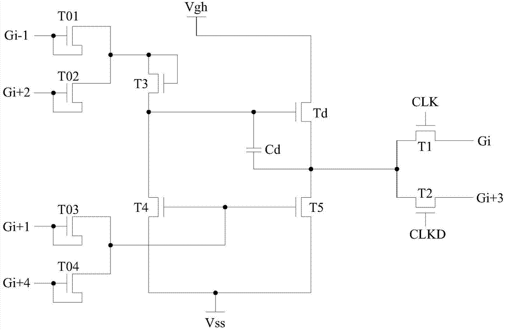
[0059] This embodiment is a more specific implementation on the basis of Embodiment 1, such as image 3 As shown, in this embodiment, the input module includes a capacitor Cd and an output switch Td, the two ends of Cd are respectively connected to the gate and drain of Td, and the source of Td is connected to the high-level signal line Vgh. The gate of Td (the first terminal of Cd) is used as the input terminal of the input module, and the drain of Td (the second terminal of Cd) is used as the output terminal of the input module. In this embodiment, all the switch transistors are preferably thin film transistors (Thin Film Transistor, TFT for short).

[0060] like image 3 As shown, as a preferred solution, the charging module includes a third switching tube T3. Gi-1 and Gi+2 are connected to the gate and source of T3, and the drain of T3 is connected to the input terminal of the input module, that is, the gate of Td (the first terminal of Cd).

[0061] When Gi-1 or Gi+2 o...

Embodiment 3

[0071] like Figure 5 As shown, the embodiment of the present invention provides a GOA circuit, including n gate lines, six clock signal lines that cyclically output high-level pulse signals, and several shift register units provided in Embodiment 1 and Embodiment 2.

[0072] like Figure 5 As shown, the gate of T1 in the j-th shift register unit is connected to CLK, the gate of T1 in the j+1-th shift register unit is connected to CLKB, and the gate of T1 in the j+2-th shift register unit The gate is connected to CLKC, the gate of T2 in the jth shift register unit is connected to CLKD, the gate of T2 in the j+1 shift register unit is connected to CLKE, and the gate of T2 in the j+2 shift register unit The gate of T2 is connected to CLKF.

[0073]Gi is connected to the drain of T1 in the shift register unit of the jth stage, and the shift register unit of the next stage, that is, the charging module in the shift register unit of the j+1st stage. In addition, if Gi is not the...


PUM


Abstract

The embodiment of the invention discloses a shift register unit, a GOA (gate driver on array) circuit, an array substrate and a display device, and belongs to the field of display techniques. The area, occupied by the GOA circuit, of the array substrate is reduced, and the requirements on narrow side frames of the array substrate are met. The shift register unit comprises an input module, a charge module and a resetting module; the output end of the input module is connected with a first grid line Gi by virtue of a first switching tube T1, and is connected with a (i+3)th grid line Gi+3 by virtue of a second switching tube T2; the grid electrode of the T1 is connected with a first clock signal wire; the grid electrode of the T2 is connected with a second clock signal wire; moreover, the phase difference of the first and second clock signal wires is a half cycle; a (i-1)th grid line Gi-1 and a (i+2)th grid line Gi+2 are connected to the input end of the input module by virtue of the charge module; a (i+1)th grid line Gi+1 and a (i+4) grid line Gi+4 are connected to the input end and the output end of the input module by virtue of the resetting module. The shift register unit, the GOA circuit and the array substrate can be applied to display devices such as an LCD TV (Liquid Crystal Display Television), a mobile phone and a tablet PC (personal computer).

Description

technical field [0001] The invention belongs to the field of display technology, and in particular relates to a shift register unit, a GOA circuit array substrate and a display device. Background technique [0002] With the continuous development of display technology, displays driven by thin film transistors have dominated the flat panel display field, such as liquid crystal displays (Liquid Crystal Display, TFT-LCD for short), organic light-emitting diodes (Organic Light-Emitting Diode, short for short) OLED) displays, etc. At present, more and more displays adopt the technology of making gate driver on array (Gate driver On Array, GOA for short) on the array substrate, so as to reduce the frame width of the array substrate of the display. [0003] The existing GOA circuit is mainly composed of several shift register units, and each shift register unit corresponds to a gate line. Its functions mainly include: using the high-level signal output by the previous row of gate ...

Claims


Application Information

Patent Timeline
IPC IPC(8): G09G3/20G11C19/28
CPCG11C19/28G09G3/2096G09G2310/0286
Inventor 徐向阳
Owner HEFEI BOE OPTOELECTRONICS TECH
Why Eureka
Try Eureka