
Gate driving circuit

A technology of gate drive circuit and level gate, which is applied in the direction of instruments and static indicators, can solve the problems of poor turn-off characteristics of switching elements, affecting the normal operation of the gate drive circuit, and disordered function of the gate drive circuit. The effect of reducing the risk of abnormality and reducing the threshold voltage offset

Active Publication Date: 2014-01-08
KUSN INFOVISION OPTOELECTRONICS
View PDF5 Cites 6 Cited by
  • Summary
  • Abstract
  • Description
  • Claims
  • Application Information

AI Technical Summary

Problems solved by technology

However, when the gate of the switching element is applied with a positive voltage for too long, its threshold voltage will shift to the right, which will cause the charging capacity of the switching element to decrease. For a long time, its threshold voltage will shift to the left, which will cause the leakage current of the switching element to be too large, and make the turn-off characteristic of the switching element worse.
When the gate drive circuit works for too long, due to the offset of the threshold voltage of the switching element, the function of the gate drive circuit may be disordered, which will affect the normal operation of the gate drive circuit

Method used


Image

  • Gate driving circuit
  • Gate driving circuit
  • Gate driving circuit

Examples


no. 1 example

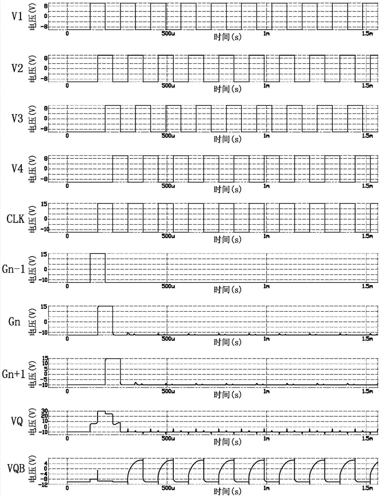
[0037] See figure 2 , Which is a timing diagram of the gate driving unit of the first embodiment, such as figure 2 As shown, the absolute values ​​of the high level and low level of the first to fourth timing signals V1 to V4 are equal, and the duty ratios of the first to fourth timing signals V1 to V4 are all percent fifty. The first timing signal to the fourth timing signal V1 to V4 are delayed by a quarter of a period in turn, that is to say, the second timing signal V2 is one quarter period later than the first timing signal V1, and the third timing signal V3 is The second timing signal V2 is one quarter period later, and the fourth timing signal V4 is one quarter period later than the third timing signal V3. The fifth timing signal CLK is synchronized with the second timing signal V2.

[0038] In an embodiment of the present invention, the high level of the first to fourth timing signals V1 to V4 is 10 volts (V), the high level of the fifth timing signal CLK is 15V, and t...

no. 2 example

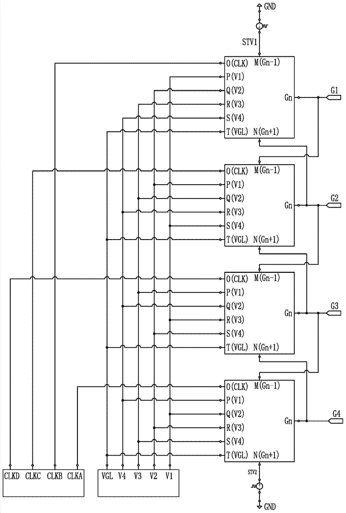
[0058] Figure 5 It is a timing diagram of the four-stage gate driving unit in the gate driving circuit of the second embodiment of the present invention. Such as Figure 5 As shown, the high level of the first to fourth timing signals V1 to V4 is three times the absolute value of the low level, and the duty ratios of the first to fourth timing signals V1 to V4 are all 100 Twenty-five. That is, the product of the amplitude of the high level and the duration of the high level of the first to fourth timing signals V1 to V4 is equal to the product of the amplitude of the low level and the duration of the low level, so The first to fourth switching elements M1 to M4, the fiftieth switching element M5, and the tenth switching element M10 have a voltage offset when a positive voltage is applied and a threshold voltage offset when a negative voltage is applied. As a result, the left and right deviation of the threshold voltage in the gate drive unit can be offset, so that the thresho...


PUM


Abstract

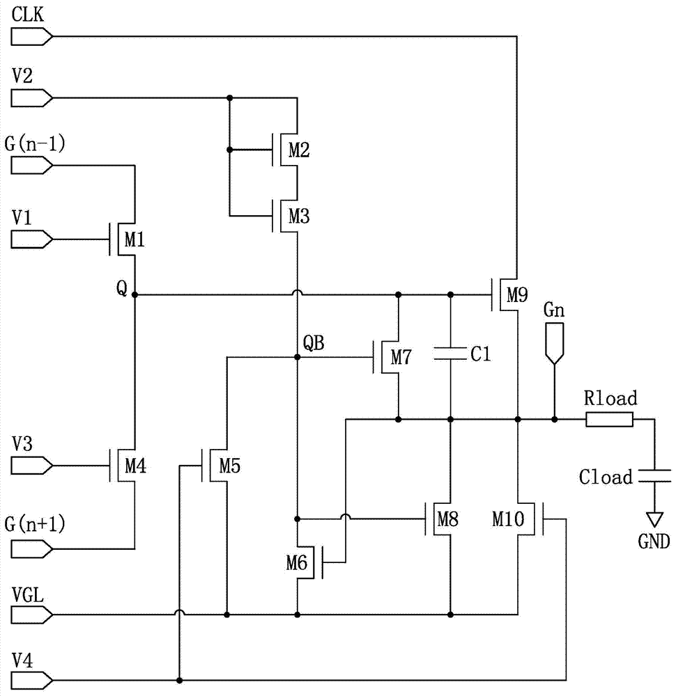
The invention provides a gate driving circuit. The gate driving circuit comprises multiple grades of gate driving units, wherein each grade of gate driving unit comprises first to tenth switch elements, a first time sequence signal, or a second time sequence signal, or a third time sequence signal or a fourth time sequence signal is received by the control ends of the first to fourth switch elements and the control end of the tenth switch element, and the absolute value ratio of the high levels of the first to fourth time sequence signals to the low levels of the first to fourth time sequence signals is equal to the difference between the reciprocal of a duty ratio and one. In the gate driving circuit, as the absolute value ratio of the high levels to the low levels of the time sequence signals received by the control ends of the switch elements is equal to the difference between the reciprocal of the duty ratio and one, threshold voltage offsets produced when a positive voltage and a negative voltage are applied on part of the switch elements are opposite numbers, and the left and right offsets of threshold voltages in the gate driving circuit can be neutralized so as to reduce the threshold voltage offsets of the gate driving circuit, thereby reducing the risk of the abnormal gate driving circuit.

Description

Technical field [0001] The invention relates to a driving circuit, in particular to a gate driving circuit suitable for a liquid crystal display device. Background technique [0002] Liquid Crystal Display (LCD) has many advantages such as lightness, thinness, energy saving, and no radiation, so it has gradually replaced the traditional cathode ray tube (CRT) display. At present, liquid crystal displays are widely used in high-definition digital televisions, desktop computers, personal digital assistants (PDAs), notebook computers, mobile phones, digital cameras and other electronic devices. [0003] Taking a thin film transistor (TFT) liquid crystal display device as an example, it includes: a liquid crystal display panel and a driving circuit. The liquid crystal display panel includes a plurality of gate lines and a plurality of data lines, and two adjacent gates The pole line crosses two adjacent data lines to form a pixel unit, and each pixel unit includes at least one thin fi...

Claims


Application Information

Patent Timeline
Patent Type & Authority Applications(China)
IPC IPC(8): G09G3/36
Inventor 李亚锋戴文君郑会龙
Owner KUSN INFOVISION OPTOELECTRONICS
Learn More