Modified thrust limit schedule for control of thrust asymmetry

A scheduling scheme, asymmetric technology, applied in control/regulation system, non-electric variable control, position/direction control, etc., can solve problems such as large load and resistance

Active Publication Date: 2014-01-08
THE BOEING CO
View PDF3 Cites 8 Cited by
  • Summary
  • Abstract
  • Description
  • Claims
  • Application Information

AI Technical Summary

Problems solved by technology

[0007] The disadvantage of increasing the ve...

Method used


Image

  • Modified thrust limit schedule for control of thrust asymmetry
  • Modified thrust limit schedule for control of thrust asymmetry
  • Modified thrust limit schedule for control of thrust asymmetry

Examples


Embodiment Construction

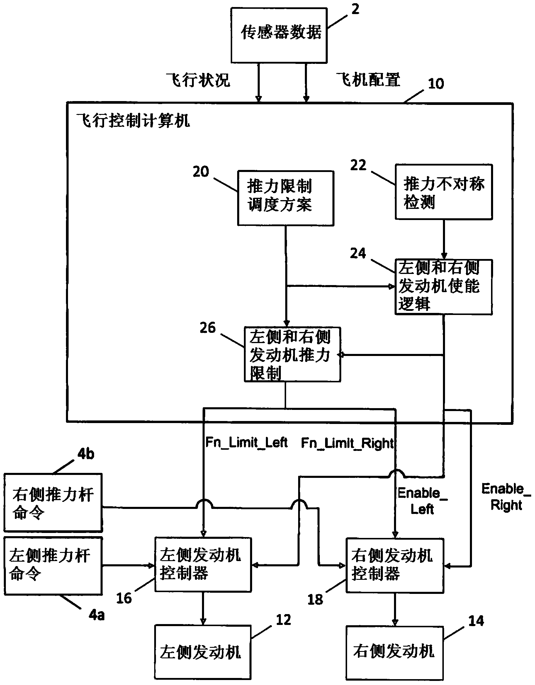
[0032] The system disclosed herein provides a variable schedule for maximum engine thrust on only one engine, which is applied during conditions of large thrust asymmetry at light loads in order to improve light load landing operations (i.e., reduce approach speed) and limit maximum thrust asymmetry. This function is implemented with high integrity signals and calculations without the use of engine sensors to detect thrust asymmetry, making the function compliant with all CFR / CS Part 25 regulations.

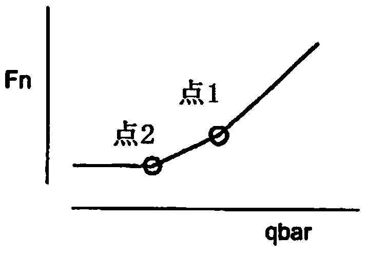
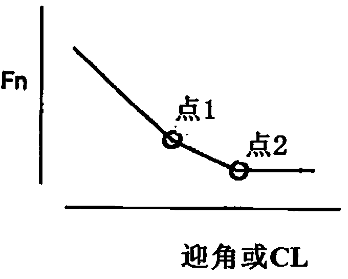
[0033] According to embodiments disclosed herein, engine thrust is controlled in the event of thrust asymmetry to reduce the airspeed required to control the thrust asymmetry. This is done by defining a reduced thrust limiting schedule that is less than the engine's normal operating capability (i.e. the reduced thrust limiting schedule controls the maximum thrust on the running engine to a lower value than the nominal thrust limiting schedule ).

[0034] The reduced thrust limi...


PUM


Abstract

A flight control and engine control function for a multi-engine aircraft which automatically controls maximum thrust on the operating engine to a value lower than the nominal thrust limit schedule in the event of loss of thrust on another engine. The maximum engine thrust of the operating engine is controlled (limited) such that the resulting thrust asymmetry can be controlled at airspeeds lower than would otherwise be the case. The decrease in engine-out minimum control speed can reduce the limitation on landing speeds that would otherwise be caused by engine-out minimum control speed.

Description

technical field [0001] The present invention generally relates to improving automatic control of multi-engine aircraft experiencing engine thrust asymmetry. Background technique [0002] Large aircraft have a wide range of operating loads. The engine is sized to achieve the desired performance under heavier loads. This allows the aircraft to have much more power at light operating loads than is required to achieve the desired performance at that load. [0003] The landing speed is set to be greater than the wing lift limiting speed or the engine output minimum control speed. The lift limiting speed is required to be at least 23% greater than the stall speed and is therefore a direct function of the aircraft weight. A large aircraft with very little payload and fuel can land at a much lower speed than the same aircraft with a larger payload. The engine output minimum control speed is determined to be the airspeed at which engine failure can be controlled with full thrust ...

Claims


Application Information

Patent Timeline
IPC IPC(8): B64D31/10G05D1/00
CPCG05D1/0072B64D31/10
Inventor D·P·艾戈德E·W·约翰森L·M·库埃E·G·科罗娜
Owner THE BOEING CO
Why Eureka
Try Eureka