Pressure control valve

A technology of pressure regulation and valve body, applied in the field of pressure regulating valve, can solve the problems of increased oil consumption, complex structure, difficult manufacture, etc., and achieve the effect of reducing the number of parts, saving costs, and improving the reliability of operation

Inactive Publication Date: 2014-01-08
UNICK
View PDF8 Cites 6 Cited by
  • Summary
  • Abstract
  • Description
  • Claims
  • Application Information

AI Technical Summary

Problems solved by technology

In particular, ball and cone (poppet) pressure regulating valves usually use a two-way (2-way) method. When the regulating pressure is zero, all the fluid supplied by the hydraulic pump is discharged, and the oil consumption increases. Therefore, Considering the effici

Method used


Image

  • Pressure control valve
  • Pressure control valve
  • Pressure control valve

Examples


Embodiment Construction

[0021] Embodiments according to the present invention will be described in detail with reference to the drawings. Hereinafter, when describing an embodiment according to the present invention and assigning reference numerals to constituent elements in each drawing, even if they appear in different drawings, the same constituent elements are assigned the same numerals as much as possible.

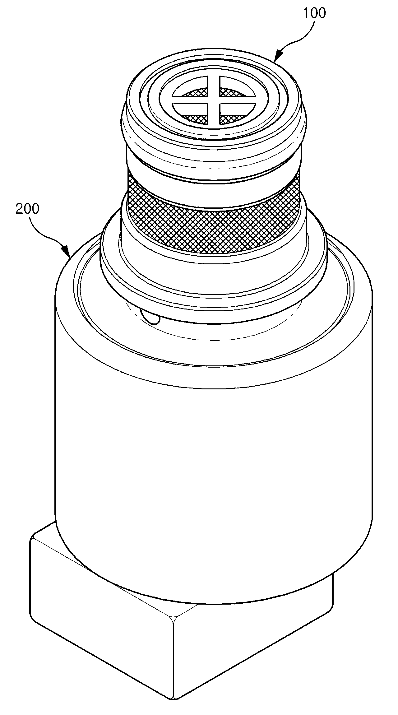
[0022] figure 1 It is an oblique view of a pressure regulating valve according to an embodiment of the present invention.

[0023] Such as figure 1 As shown, according to the pressure regulating valve of this embodiment, the valve portion 100 supplied to the clutch side by applying a certain regulation pressure to the fluid supplied from the outside and adjusting the opening amount of the valve portion 100 according to the value of the current applied from the outside Thus, the electromagnetic part 200 for adjusting the adjustment pressure is constituted.

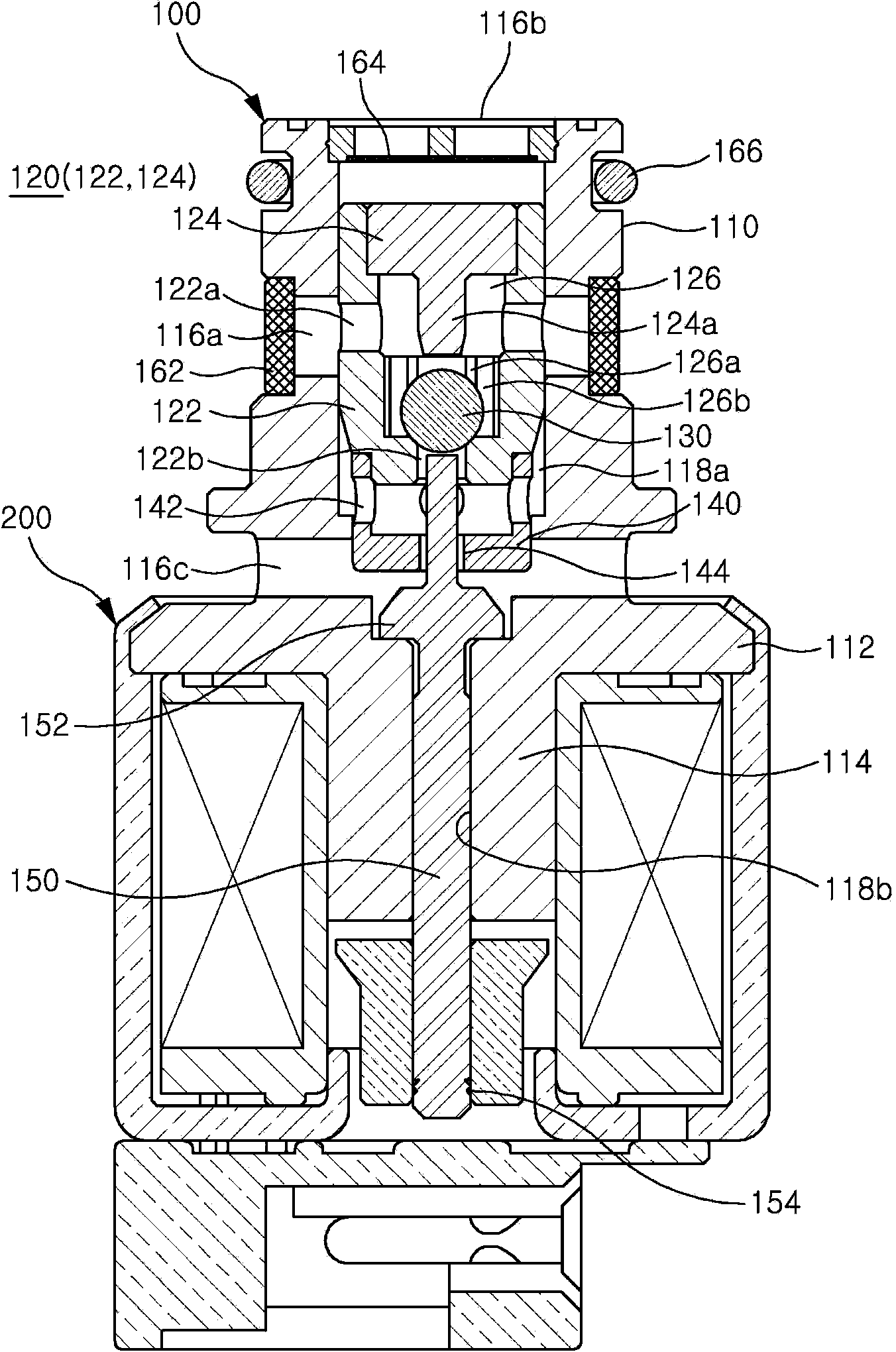
[0024] refer to Figure 2 to F...


PUM


Abstract

Disclosed is a pressure control valve used in a clutch of an automatic transmission. The pressure control valve includes a valve body having a supply port, a control port and a discharge port therein; a first insert disposed inside the valve body, the first insert being formed with an inlet connected to the supply port and an outlet for discharging fluid supplied through the inlet; a ball disposed inside the first insert to open/close the outlet; a second insert coupled to the outlet side of the first insert, the second insert being formed with a first discharge hole connected to the control port and a second discharge hole connected to the discharge port; a rod movably provided to the valve body, the rod having one end extending toward the ball, the rod having a poppet formed in the middle thereof to open/close the second discharge hole; and a solenoid moving the rod. With the above structure, according to a current value applied on the solenoid, the outlet of the first insert and a second discharge hole of the second insert are opened and closed by use of the ball and the poppet, or the opening degree is adjusted, thereby effectively adjusting the pressure of the fluid discharged through the control port, and preventing unnecessary waste of the fluid.

Description

technical field [0001] The invention relates to a pressure regulating valve for a clutch of an automatic transmission, in particular to a proportional regulating valve for regulating fluid pressure according to a current value. Background technique [0002] Generally, a transmission is a speed change device that converts the power generated by the engine into the required rotational force according to the speed and transmits it. This transmission is divided into: a manual transmission in which the speed change process is realized through the driver's manual conversion and an automatic transmission in which the speed change process is automatically realized according to a certain pattern. [0003] The above-mentioned automatic transmission includes: a torque converter, a rotating device, a planetary gear device, a multi-plate clutch, an oil pressure control device, and an electronic control device. Among them, the multi-plate clutch consists of a clutch cage, a plurality of ...

Claims


Application Information

Patent Timeline
IPC IPC(8): F16H61/02F16K31/06
CPCF16K31/0665F16H2061/0258F16H61/0251F16H2061/0253F16H57/02F16K31/00F16K31/06
Inventor 李昌勋鲁义东安赞植柳善钟
Owner UNICK
Why Eureka
Try Eureka