Supercharge Your Innovation With Domain-Expert AI Agents!

Electric machine

An electrical and mechanical technology, applied in the direction of electrical components, electromechanical devices, DC commutators, etc., can solve the problems of acoustic damage, undesired, loss, etc.

Active Publication Date: 2014-01-08
FEAAM
View PDF7 Cites 6 Cited by
  • Summary
  • Abstract
  • Description
  • Claims
  • Application Information

AI Technical Summary

Problems solved by technology

All harmonic components other than those used as operating waves for the motor are undesirable as they cause losses and also cause undesirable, especially acoustic damage

Method used


Image

  • Electric machine
  • Electric machine
  • Electric machine

Examples


Embodiment Construction

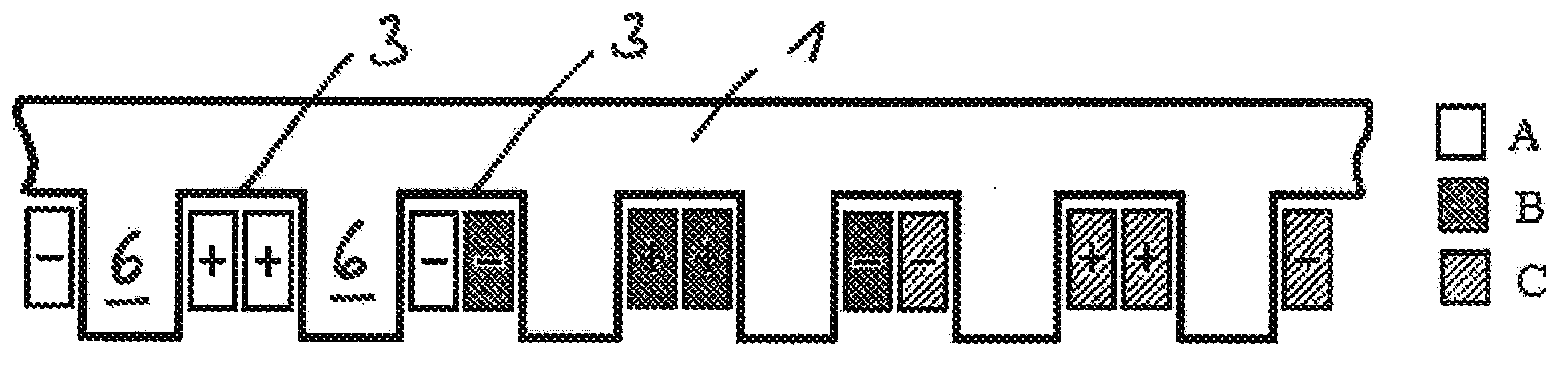
[0063] figure 1 The topology of the winding system with three phases A, B, C is shown. according to figure 1 The number of electrical phases of the electrical winding system totals three, thus corresponding to the electrical phase number 3 of the electrical system to which three strings of winding systems can be connected. The number of electrical phases is denoted by m.

[0064] The stator 1 with the installed winding system comprises six slots. The number of slots is represented by Z. For the purpose of simplifying the description, the stator 1 and the winding system installed therein are shown in an unrolled linear appearance, but could alternatively be realized as a rotating electrical machine comprising a stator of circular cross-section. In the case of a linear motor, the stator cross-section shown can be repeated periodically.

[0065] In addition, according to figure 1 The electrical windings of the are characterized in that they are concentrated windings in whic...


PUM


Abstract

The proposed principle relates to an electric machine having a stator (1) and a rotor (2) that can move relative to the stator. The stator (1) comprises a first and at least one second winding system (4, 5) that have coils, each of which is placed in stator grooves (3) and is wound around stator teeth (6). The first winding system (4) and the second winding system (5) each have at least one tooth (7) around which no coil is wound. When combining the first and the second winding system (4, 5), all teeth of the stator (1) have coils wound around them.

Description

technical field [0001] The present invention relates to a motor. Background technique [0002] A motor generally includes a stator with a fixed casing and a rotor that can move relative to the stator. The rotor may be supported, for example, so as to be able to rotate or move linearly relative to the stator. [0003] Electric machines are classified as electromechanical energy converters. They can operate as electric motors or generators. [0004] For example, electric machines may be used to power motor vehicles. Here, specific properties of motor operation behavior are desired. These properties include, for example: torque, acoustic properties, iron losses and losses in permanent magnets (if used), and losses in motor windings. A motor with concentrated windings is differentiated by a compact design and simplified manufacturing compared to a motor with distributed windings. [0005] In particular, polyphase electric machines are prevalent in vehicle drive systems, ma...

Claims


Application Information

Patent Timeline
Patent Type & Authority Applications(China)
IPC IPC(8): H02K3/28
CPCH02K3/28H02K3/12H02K23/24
Inventor 古拉克·达亚库
Owner FEAAM
Features
  • R&D
  • Intellectual Property
  • Life Sciences
  • Materials
  • Tech Scout
  • Unparalleled Data Quality
  • Higher Quality Content
  • 60% Fewer Hallucinations
Learn More