Saw blade right-angle head

An angle head and right-angle technology, applied in the field of saw blade right-angle head, can solve the problems of cumbersome and complicated assembly process, increase processing time, strict assembly requirements, etc. Effect

Inactive Publication Date: 2014-01-15
佛山市永信模具有限公司
View PDF8 Cites 4 Cited by
  • Summary
  • Abstract
  • Description
  • Claims
  • Application Information

AI Technical Summary

Problems solved by technology

In the prior art, the assembly process of the positioning block 7 and the positioning pin 8 is relatively cumbersome and complicated. In order to ensure good stability of the angle head after installation, the assembly relationship between the two is relatively tense, thereby increasing the processing time
The overall center of gravity of the angle head in the prior art tends to the position of the tool, and the length of the driving shaft of the angle head is relatively long. If the centering of the driving shaft of the angle head is poor, it will cause the centrifugal phenomenon of the driving shaft of the angle head during the processing process, which will also cause the angle The overall processing strength of the head is reduced
The structure of the angle head used to adjust the horizontal angle of the angle head in the prior art is located under the positioning pin 8 and the positioning block 7, so the assembly requirements for the positioning block 7 and the positioning pin 8 are more stringent

Method used


Image

  • Saw blade right-angle head
  • Saw blade right-angle head
  • Saw blade right-angle head

Examples


Embodiment Construction

[0013] The present invention will be further described below in conjunction with a specific embodiment.

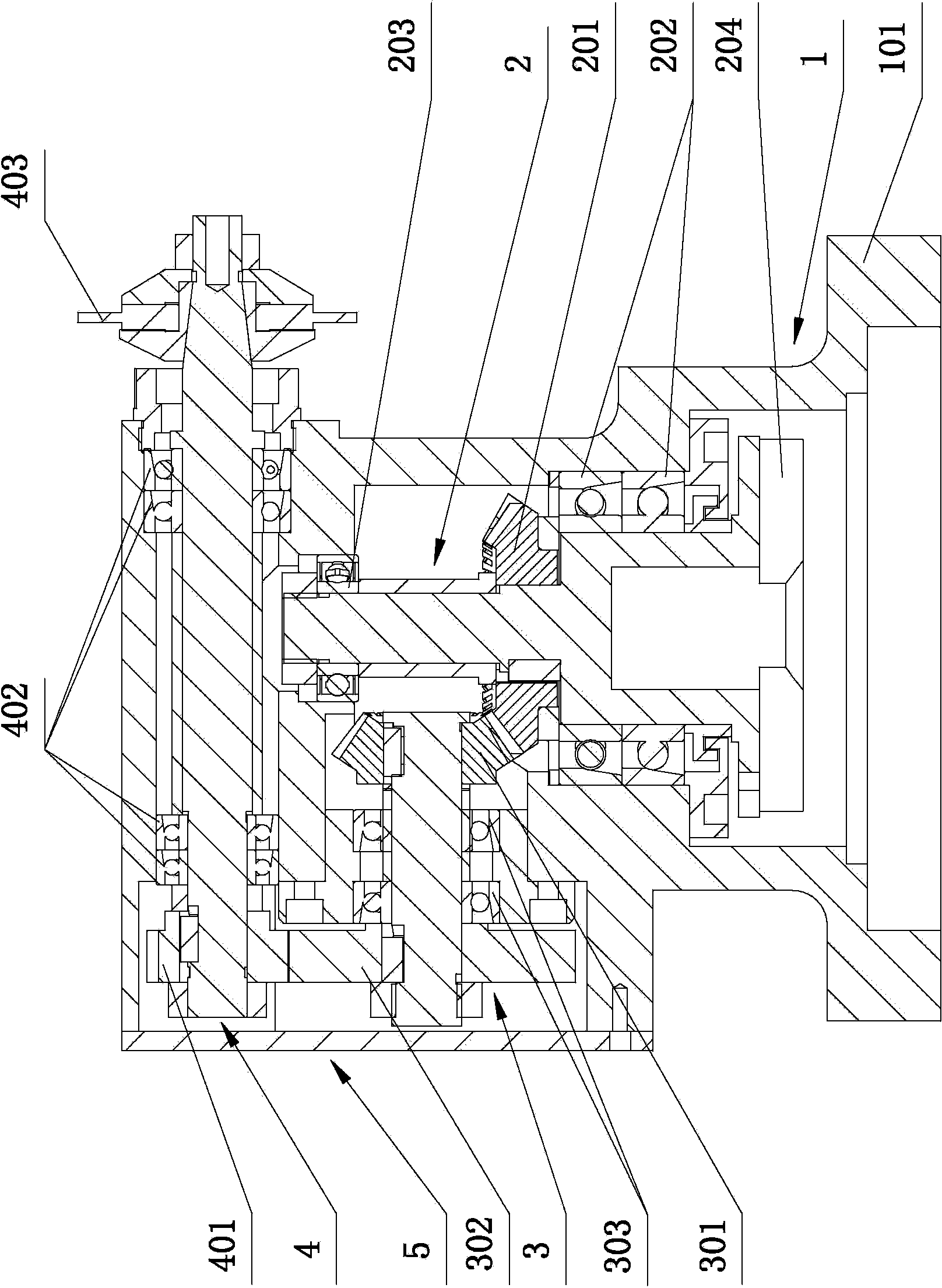
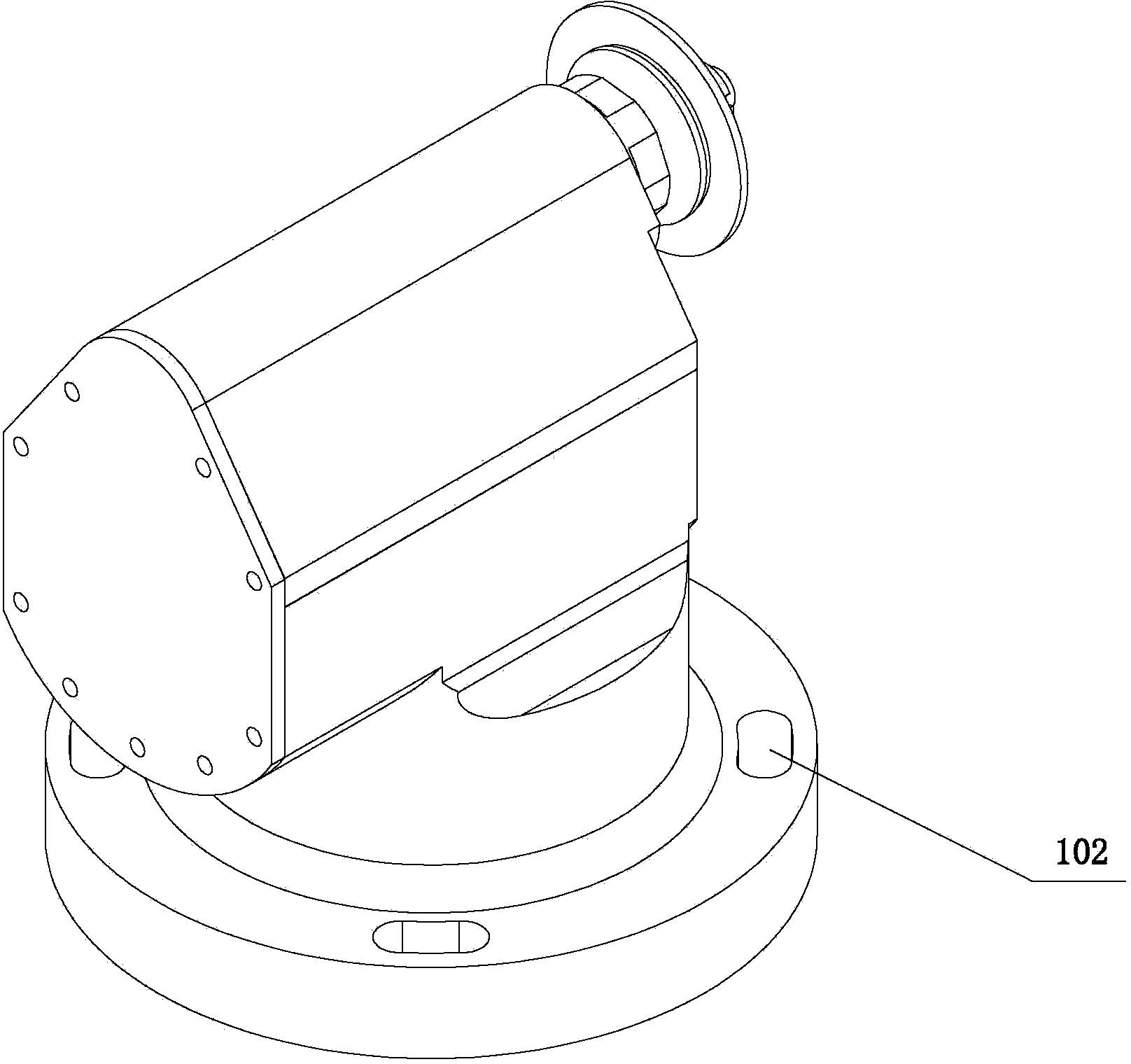
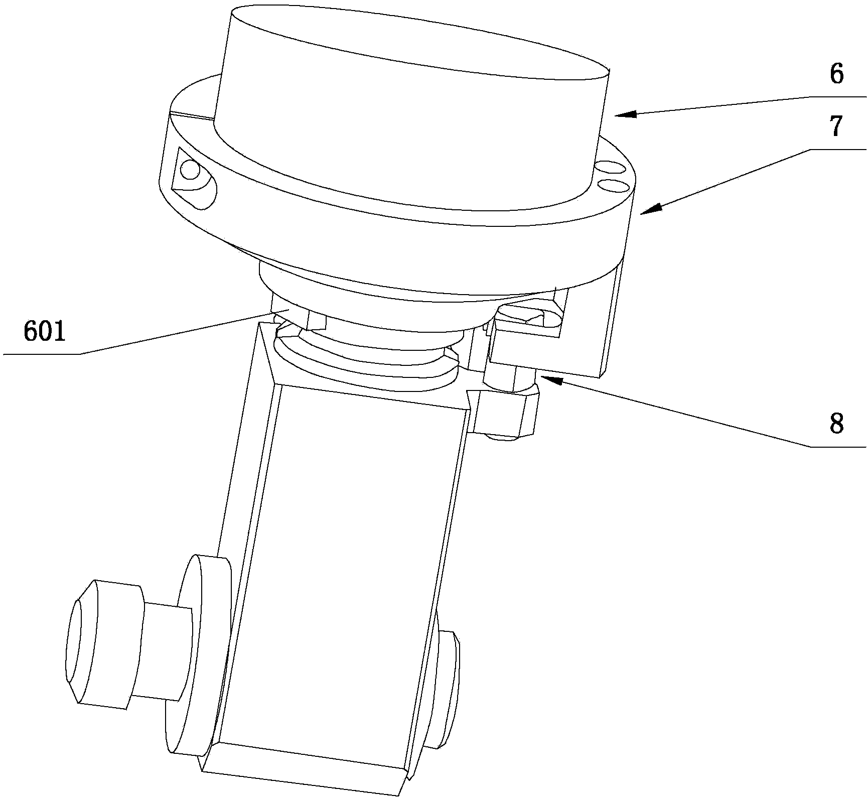
[0014] See attached figure 1 And attached image 3 As shown, this embodiment includes an angle head main body 1 , a driving shaft 2 , a driven shaft 3 , a saw blade shaft 4 , and an end cover 5 . When the angle head main body 1 is placed vertically, the driving shaft 2 is installed at the vertical center position of the lower part of the angle head main body 1 . Two angular contact ball bearings 202 are installed on the drive shaft 2 close to the chassis flange 101 , and the two angular contact ball bearings 202 are in contact and have the same installation direction. A deep groove ball bearing 203 is installed at a position away from the chassis flange 101 , and the three together ensure the centering of the drive shaft 2 inside the angle head main body 1 and the rigidity of the drive shaft 2 . A bevel gear 201 is installed between the deep groove ball bearing 203 and ...


PUM


Abstract

A saw blade right-angle head comprises an angle head body, a driving shaft, a driven shaft, a saw blade shaft and an end cover, wherein the driven shaft is arranged on the lower portion of the angle head body, the driving shaft is perpendicular to the driven shaft, and the driven shaft is parallel with the saw blade shaft; an angle gear of the driving shaft is matched with an angle gear assembled on the driven shaft, a straight gear of the driven shaft is matched with a straight gear of the saw blade shaft, the gravity center of the angle head body is inclined downwards, and kidney-shaped holes are formed in a base plate flange of the angle head body. An angular contact ball bearing and a deep groove ball bearing are arranged on the driving shaft, angular contact ball bearings are arranged on the driven shaft, the angular contact ball bearings of the driven shaft are arranged at certain intervals, and two angular contact ball bearings are arranged on the saw blade shaft. A key groove is formed in the bottom of the driving shaft and matched with a transmission key block of the driving shaft. The kidney-shaped holes are evenly distributed in the circumferential direction with the driving shaft as a center line. According to the saw blade right-angle head, the angle head body and the driving shaft are directly installed, the angle head is directly installed on a lathe, and the position of the angle head is adjusted through the kidney-shaped holes. The angle head can save assembling and replacing time and guarantee assembling accuracy.

Description

technical field [0001] The invention relates to the technical field of mechanical processing, in particular to a saw blade right angle head. Background technique [0002] The angle head is an accessory of the machine tool. After the machine tool is equipped with the angle head, the rotation center line of the tool can form a certain angle with the rotation center line of the machine tool spindle to process the workpiece. Because the angle head does not need to change the original structure of the machine tool, it can increase the processing range of the machine tool and improve its processing adaptability, so that the angle head can be widely used in various fields such as aerospace, automobile, mold and other mechanical processing. [0003] In the existing technology, such as image 3 , The positioning of the angle head mainly depends on the positioning pin 8 on the angle head and the positioning block 7 installed on the machine tool spindle 6 to cooperate and fix. In the ...

Claims


Application Information

Patent Timeline
Patent Type & Authority Applications(China)
IPC IPC(8): B23D59/00B23Q3/12
Inventor 李爱军
Owner 佛山市永信模具有限公司
Why Eureka
Try Eureka