Long-range conveying haversack throwing machine

A technology of remote conveying and grain throwing machine, which is applied in the direction of throwing machine, transportation and packaging, etc. It can solve the problems of high labor intensity, low efficiency, labor and time-consuming, etc., and achieve convenient processing and production, good use effect and simple structure Effect

Inactive Publication Date: 2014-01-15
杨可秀
View PDF7 Cites 8 Cited by
  • Summary
  • Abstract
  • Description
  • Claims
  • Application Information

AI Technical Summary

Problems solved by technology

[0002] Due to the limitations of its structural design, the conveyors currently used in the granary cannot meet the needs of high-altit

Method used


Image

  • Long-range conveying haversack throwing machine

Examples


Embodiment Construction

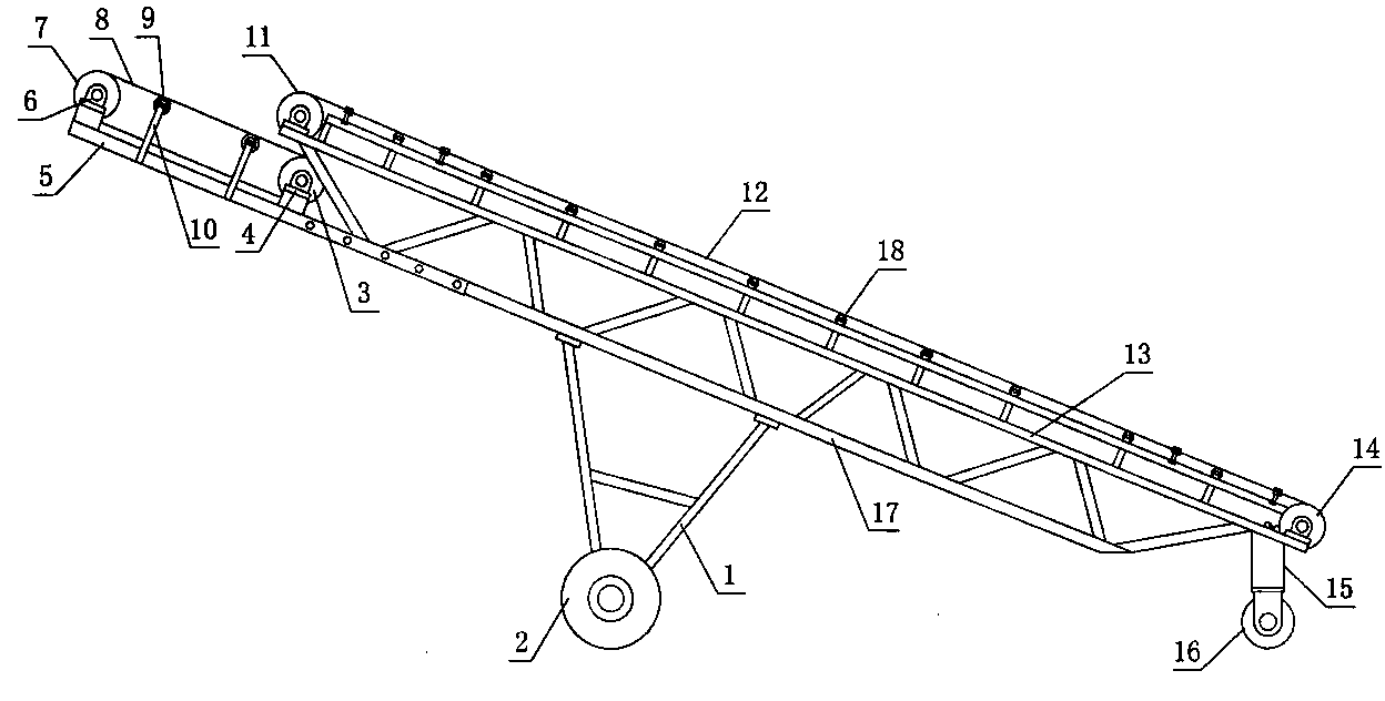
[0009] figure 1 The lower end of the upper frame 13 shown in is provided with a lower frame 17, the lower end of the lower frame is provided with a front support 1, the rear side of the front support is provided with a rear support 15, and the bottom end of the front support is provided with a front traveling wheel 2 , the rear steering wheel 16 is installed at the bottom of the rear support, the front upper end of the upper frame is provided with a motor roller 11, the rear upper end of the upper frame is provided with a rear roller 14, and the rear roller is installed on the rear of the upper frame by the rear roller bracket. On the upper end, the front end of the rear roller support is provided with a conveyer belt tightness adjusting bolt, and the upper conveyer belt 12 is housed on the rear roller and the motor roller, and a row of support rollers 18 is provided on the bottom side of the upper conveyer belt. The front lower end of the upper frame is provided with a grain ...


PUM


Abstract

The invention discloses a long-range conveying haversack throwing machine. A lower machine frame is arranged at the lower end of an upper machine frame, a front support is arranged at the lower end of the lower machine frame, the bottom end of the front support is provided with a front travelling wheel, the bottom end of a rear support is provided with a rear steering wheel, the front upper end of the upper machine frame is provided with a motor roller, and the rear upper end of the upper machine frame is provided with a rear roller, an upper conveying belt is arranged on the rear roller and the motor roller, and the front lower end of the upper machine frame is provided with a haversack throwing frame. The front end of the haversack throwing frame is provided with an upper bearing block, the rear end of the haversack throwing frame is provided with a lower bearing block, the front end of the haversack throwing frame is provided with a high-speed motor roller, the rear end of the haversack throwing frame is provided with a follow-up roller, a haversack throwing conveying belt is arranged at the upper end of the high-speed motor roller and the upper end of the follow-up roller, and the lower side of the haversack throwing conveying belt is provided with a riding wheel frame. When the long-range conveying haversack throwing machine is used, haversacks are conveyed to the top end through the upper conveying belt, fall onto the haversack throwing conveying belt, are conveyed through the high-speed rotating haversack throwing conveying belt at high speed, and are thrown to front upper space under the action of inertia.

Description

technical field [0001] The invention relates to a kind of grain conveying equipment, to be precise, it is a kind of relay grain throwing machine for grain conveying. Background technique [0002] Due to the limitations of its structural design, the conveyors currently used in the granary cannot meet the needs of high-altitude stacking. The upper space in the warehouse cannot be transported in place, and manual climbing and stacking is still required. Low. Contents of the invention [0003] The purpose of the present invention is to overcome the above-mentioned defects and provide a remote grain conveying and throwing machine to save manpower, improve work efficiency, and meet the needs of high-altitude stacking of granaries. [0004] The scheme of the present invention is composed of an upper frame, a lower frame, front and rear brackets, and high and low speed motors. The rear side of the support is provided with a rear support, the bottom end of the front support is pr...

Claims


Application Information

Patent Timeline
IPC IPC(8): B65G31/02
Inventor 黄毅杨可秀
Owner 杨可秀
Why Eureka
Try Eureka