
Electronic element feeding device and application device comprising same

A technology of electronic components and feeding devices, which is applied in the direction of cleaning devices, conveyor objects, transportation and packaging, etc., can solve the problems of increasing the inconvenience of feeding operations, time-consuming elimination of alarms, and increasing the workload of staff, so as to improve the convenience of operation, The effect of preventing material jam

Inactive Publication Date: 2014-01-15
PROV TECH CORP
View PDF6 Cites 4 Cited by
  • Summary
  • Abstract
  • Description
  • Claims
  • Application Information

AI Technical Summary

Problems solved by technology

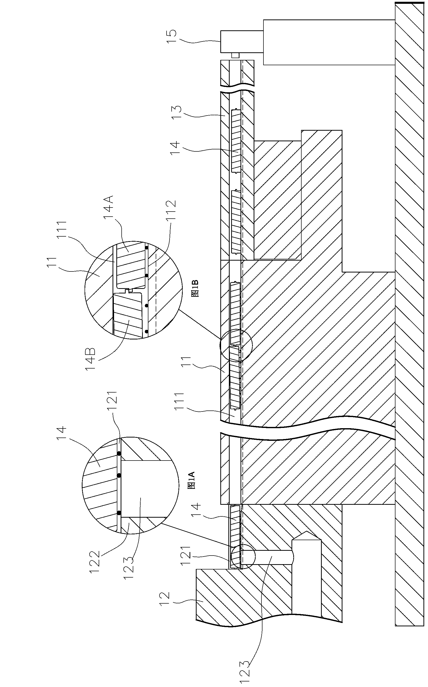
[0003] Since the two ends of each electronic component 14A, 14B will have edge material, when the blowing device 15 blows each electronic component 14A, 14B and slides in the material channel 111, the rear electronic component 14A is likely to be stuck by the edge material. The edge material of the component 14B causes the front and rear electronic components 14A and 14B to overlap each other and get stuck in the material channel 111. The staff must continue to use tools to separate the two electronic components 14A and 14B in order to eliminate the abnormal state, not only Quite tedious and time-consuming, which increases the workload of the staff
[0004] The staff touches the electronic components 14A and 14B of the second card material with a tool, and pushes and pushes the front and rear electronic components 14A and 14B to separate, causing the surface of each electronic component 14A and 14B to be easily scratched by the tool, resulting in additional component damage lack of
[0005] Since the bottom surface of the electronic components 14A, 14B or the material channel 111 of the feeder 11 will be attached with dust debris, when each electronic component 14A, 14B slides on the bearing part 112 of the material channel 111, it is easy to be caused by dust debris. Chips are stuck in the material channel 11, which in turn affects the smoothness of the subsequent electronic component delivery, resulting in the inconvenience of increasing the feeding operation.
[0006] When dust and debris are blown to the bearing portion 122 of the carrier 12 along with the electronic components 14, the electronic components 14 will not be able to completely close the suction hole 123 due to the dust and debris on the bottom surface, causing the suction hole 123 to be unable to vacuum absorb the electronic component 14 for positioning, so that The central control device (not shown in the figure) misjudged that there was no electronic component 14 on the stage 12, and issued an abnormal alarm, and the staff had to spend time to eliminate the alarm, resulting in the inconvenience of increasing the feeding operation.

Method used


Image

  • Electronic element feeding device and application device comprising same
  • Electronic element feeding device and application device comprising same
  • Electronic element feeding device and application device comprising same

Examples


Embodiment Construction

[0050] In order to make your examiner further understand the present invention, hereby give a preferred embodiment and cooperate with the drawings, as follows in detail:

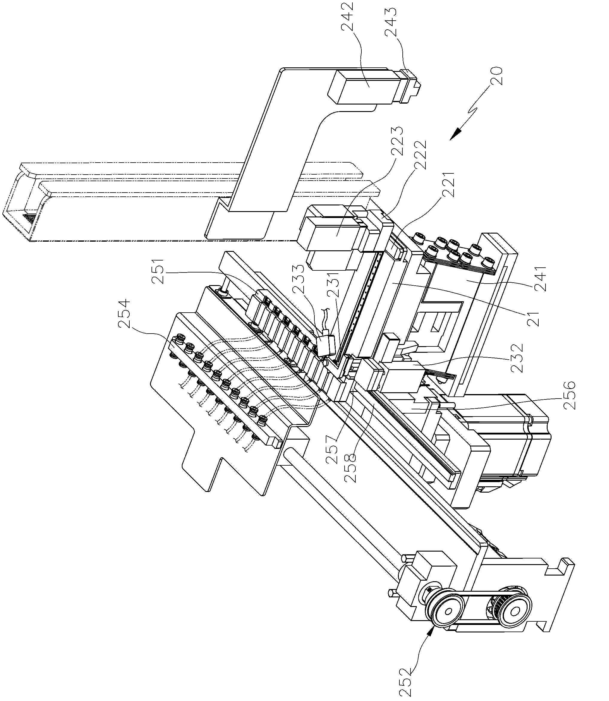
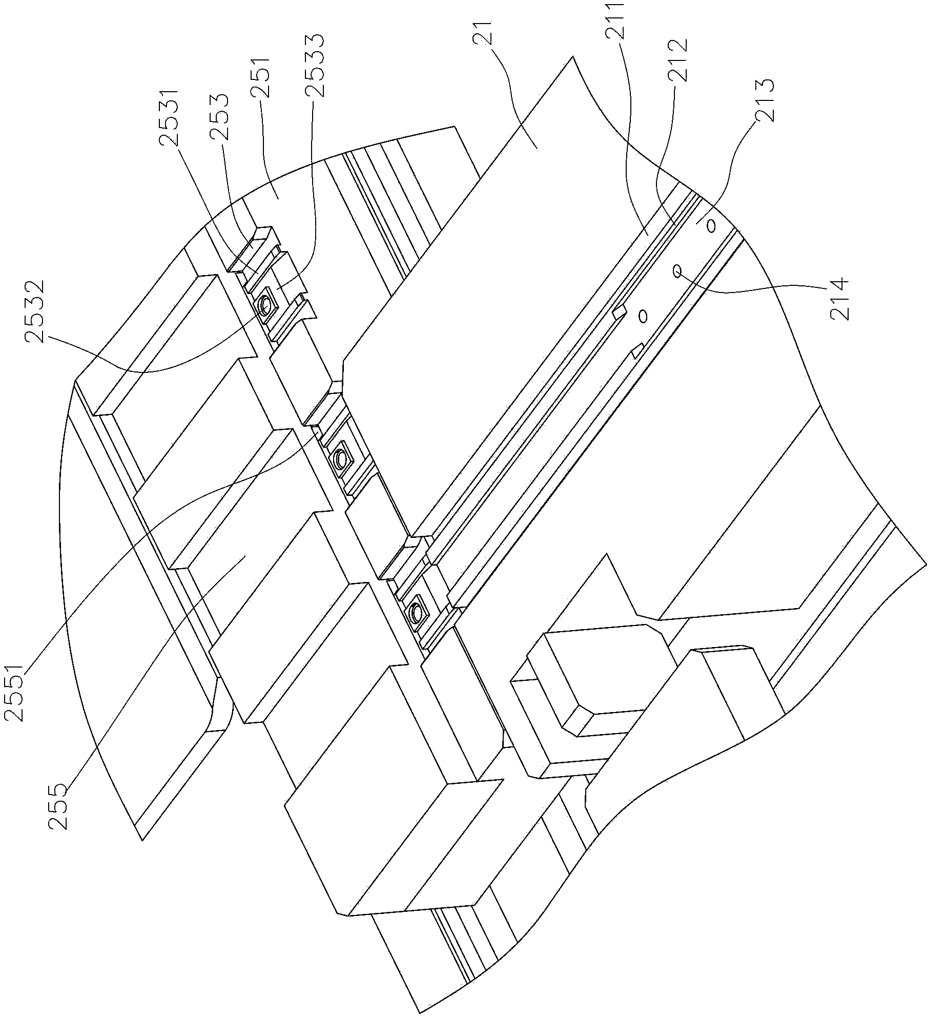
[0051] see figure 2 , image 3 The feeding device 20 of the present invention includes a feeder 21, a positioning mechanism, a limit mechanism, an anti-jamming mechanism, and a loading mechanism. The feeder 21 is provided with at least one material channel 211 that can transport electronic components. In this embodiment, The feeder 21 is placed in the first direction (such as the X direction), and the bottom surface of the feeder 211 is protruded with a bearing portion 212 of appropriate height for holding electronic components. There is an impurity discharge structure that can remove dust and debris. In this embodiment, the impurity discharge structure is provided with a dust discharge channel 213 on the bearing part 212 of the material channel 211, which can allow the dust and debris on the bottom surfac...


PUM


Abstract

The invention provides an electronic element feeding device which comprises a feeding device, an anti-blocking mechanism and a material carrying mechanism. The feeding device is provided with at least one material channel capable of conveying electronic elements, the material channel is provided with an impurity eliminating structure capable of eliminating dust and bits, the anti-blocking mechanism is provided with at least one vibrator connected with the feeding device and used for vibrating the electronic elements in the feeding device, the material carrying mechanism is provided with at least one carrying table driven by a drive source for displacement, the carrying table is used for carrying electronic elements output from the material channel, and the material carrying mechanism is further provided with a dust eliminating structure capable of eliminating dust and bits. The vibrator of the anti-blocking mechanism is used for vibrating the feeding device, so that the electronic elements in the material channel of the feeding device are separated due to vibration and are prevented from being overlapped and blocked, the electronic elements are conveyed out in the same direction, and the practical benefits of effectively preventing material blocking and improving convenience of operation are achieved.

Description

technical field [0001] The invention relates to an electronic component feeding device which can prevent material jamming and easily remove dust and debris, so as to improve the convenience of feeding operation. Background technique [0002] Nowadays, electronic components (such as IC) must go through multiple workstations. Each workstation uses different containers to hold electronic components according to the nature of the operation. The container can be a tube or a tray. When two workstations use tubes and trays respectively When storing electronic components, the industry must use a feeding device to transfer the electronic components in the material tube to the stage so that the mechanical arm can take it out and transfer it to the material tray for storage; please refer to figure 1 , figure 1 A. figure 1 B is a schematic diagram of the current feeding device. The feeding device is provided with a feeder 11 with a material channel 111 for conveying electronic compone...

Claims


Application Information

Patent Timeline
Patent Type & Authority Applications(China)
IPC IPC(8): B65G47/14B65G45/10
Inventor 陈彦玮诸柏亘陈宏达赖正鑫郑炜彦
Owner PROV TECH CORP
Learn More