Special adjusting device for crank balance weight of beam-pumping unit

A technology for adjusting devices and pumping units, which is applied in wellbore/well parts, production fluid, earthwork drilling and production, etc., which can solve problems affecting adjustment work, easy damage, and increased force, so as to save operating costs and use The effect of convenience and easy operation

Inactive Publication Date: 2014-01-15
CHINA PETROLEUM & CHEM CORP +1
View PDF8 Cites 2 Cited by
  • Summary
  • Abstract
  • Description
  • Claims
  • Application Information

AI Technical Summary

Problems solved by technology

[0004] It can be seen from this that the above-mentioned patent documents have solved several technical problems to a certain extent, but the use effect is not good and the efficiency is low. It is still laborious to run the lead screw back and forth; in addition, the lead screw is only erected on a thin L-shaped vertical side, which increases the force here, is prone to deformation and damage, and affects the adjustment work; in addition, the front end of the lead screw of this patent The thrust assembly only solves the problem of preventing non-rotation after being held against the top piece, but it cannot guarantee the stable and straight running of the screw, because during the readjustment process, the screw can easily deviate from the axis direction of the screw itself due to the force, up and down Random left and right movements directly affect the adjustment work, so the problem of the vertical movement of the screw perpendicular to the base and the left and right movement parallel to the base cannot be solved, and it cannot be guaranteed that the screw can only run along its axis

Method used


Image

  • Special adjusting device for crank balance weight of beam-pumping unit

Examples


Embodiment Construction

[0020] The detailed description and technical content of the present invention are described below with the accompanying drawings, but the accompanying drawings are only provided for reference and description, and are not intended to limit the present invention.

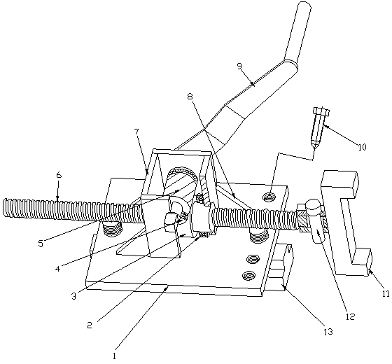
[0021] according to figure 1 As shown, a special adjustment device for the crank balance weight of a beam pumping unit is composed of four parts: a base, a transmission steering mechanism, a lead screw and a crank handle.

[0022] Base 1 is made of rectangular steel plate. A round hole that can pass through the fixing bolt 13 is respectively opened on the center line of the two narrow sides of the base 1, and two (total 4) positioning screw holes are respectively drilled on both sides of one of the round holes. The fixing bolt 13 is a common threaded bolt, with a nut on one end and an inverted T-shaped block connected by riveting and welding at the other end. The inverted T-shaped block can be packed into the T-shap...


PUM


Abstract

The invention discloses a special adjusting device of a crank balance weight of a beam-pumping unit. The adjusting device comprises a base and a lead screw arranged on the base. The base is connected into a T-shaped groove of a crank in a sliding mode through an inverted-T-shaped block. A wide U-shaped clamp head which can prevent the lead screw from moving up and down perpendicular to the base and from moving left and right parallel to the base is installed at the bearing end of the lead screw, a bayonet of the clamp head is clamped to a step at a fastening bolt of the balance weight of the beam-pumping unit in a matched mode, and one end of the clamp head stretches deep into the T-shaped groove of the crank. The lead screw is arranged on the base after being matched with a transmission steering mechanism mutually. The transmission steering mechanism comprises a cubic transmission case located in the middle of the base, a worm gear and a worm, wherein the worm gear and the worm are arranged inside the transmission case. Due to the adjusting device, balancing of the pumping unit can be performed on the ground instead of high above the ground, and thus the operation is easier and safer to perform. When the special adjusting device of the crank balance weight of the beam-pumping unit is used for adjusting balance, a crane is not needed to be in auxiliary cooperation with the adjusting device, and thus operation cost is saved. The special adjusting device of the crank balance weight of the beam-pumping unit is small in size and convenient to carry and use.

Description

technical field [0001] The invention relates to a technology for optimizing and adjusting the balance rate of a conventional beam pumping unit in oil exploitation in the petroleum industry, in particular to a special adjustment device for a crank balance block of a beam pumping unit. Background technique [0002] At present, the balancing operation of the beam pumping unit is to rotate the crank to a horizontal position, apply the brakes, and then start to adjust the balance weight above the crank: loosen the fixing bolts of the balance weight, remove the tooth-shaped lock block of the balance weight, and adjust the balance The block moves to the predetermined position, then the upper balance block tooth-shaped lock block is installed, and the balance block fixing bolt is tightened. Adjust the balance weight on the other side of the pumping unit in the same way. In this way of balancing, the operator needs to work at heights. When the crank points to the front of the pumpi...

Claims


Application Information

Patent Timeline
IPC IPC(8): E21B43/00B25B33/00
Inventor 李平吴运铎宋东锋初玉林赵栋
Owner CHINA PETROLEUM & CHEM CORP
Why Eureka
Try Eureka