Engine speed monitoring system

An engine speed, monitoring system technology, applied in the direction of machines/engines, mechanical equipment, gas turbine devices, etc., can solve problems such as cost increase, performance decline, weight increase, etc., to achieve compact structure, small size, guaranteed operation performance and reliability. Effect

Active Publication Date: 2014-01-15
CHINA AVIATION POWER MACHINE INST
View PDF4 Cites 1 Cited by
  • Summary
  • Abstract
  • Description
  • Claims
  • Application Information

AI Technical Summary

Problems solved by technology

[0005] The purpose of the present invention is to provide an engine speed monitoring system to solve the technical problem that the sensor needs to convert the speed signal by setting the end face tone wheel, which leads to cost increase, weight increase and performance decline

Method used


Image

  • Engine speed monitoring system
  • Engine speed monitoring system
  • Engine speed monitoring system

Examples


Embodiment Construction

[0024] The embodiments of the present invention will be described in detail below with reference to the accompanying drawings, but the present invention can be implemented in many different ways defined and covered by the claims.

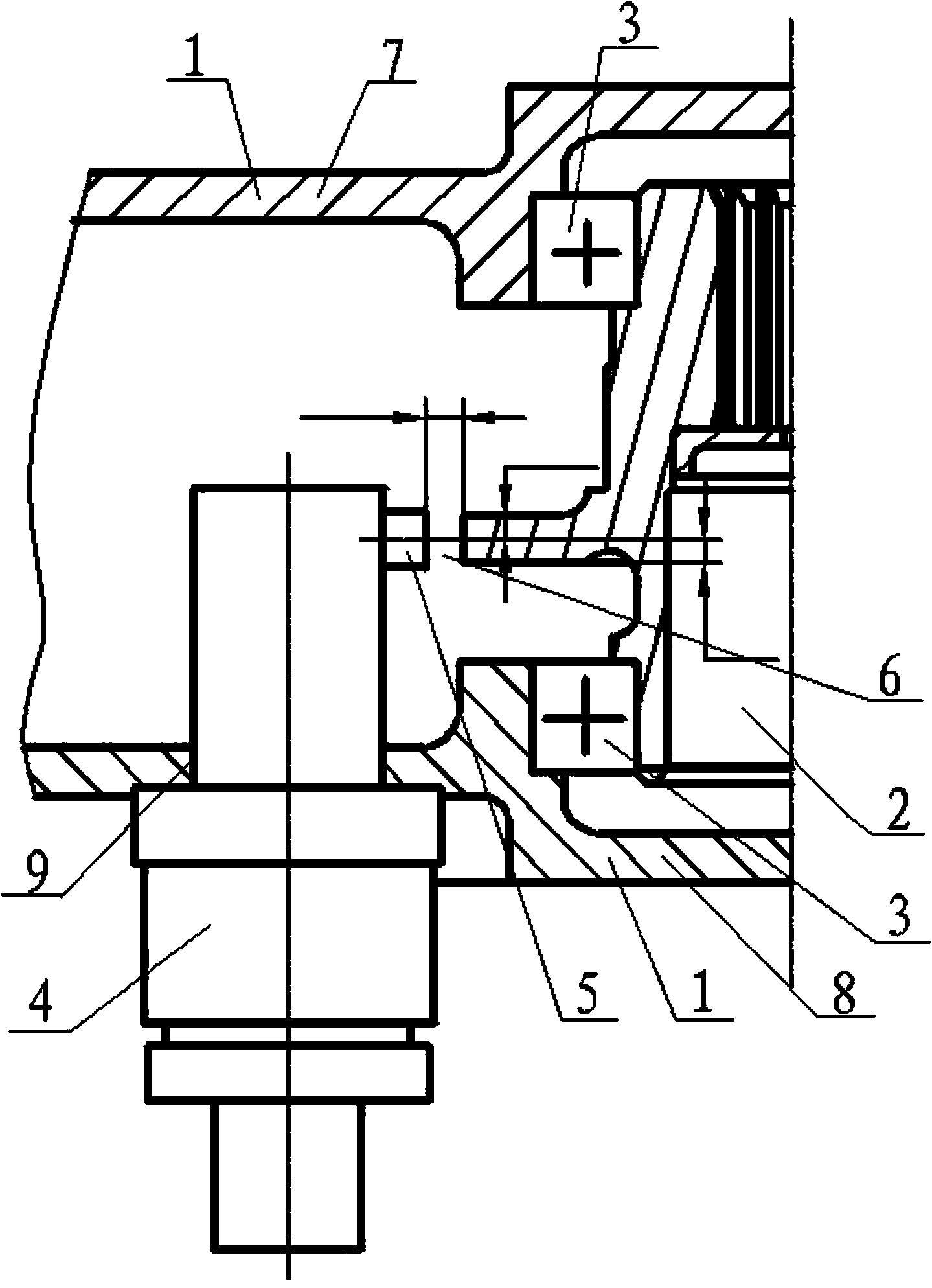
[0025] figure 1 It is a structural schematic diagram of the engine speed monitoring system of the preferred embodiment of the present invention, as figure 1 As shown, the engine speed monitoring system of this embodiment includes an accessory transmission casing 1, and a transmission gear 2 is arranged in the accessory transmission casing 1, and the transmission gear 2 is installed in the accessory transmission casing 1 through a supporting bearing 3. A magnetoelectric speed sensor 4 whose main center line is parallel to the axis of the transmission gear 2 is installed on the box 1, and an induction boss 5 is arranged on the magnetoelectric speed sensor 4, and the induction boss 5 is arranged on the surface of the magnetoelectric speed sensor 4 , t...


PUM


Abstract

The invention discloses an engine speed monitoring system which comprises an accessory drive casing (1); a transmission gear (2) is arranged in the accessory drive casing (1) through a supporting bearing (3); a magnetoelectric tachometric transducer (4) with the main center line parallel to the axis of the transmission gear (2) is mounted on the accessory drive casing (1); an induction boss (5) is arranged on the surface of the magnetoelectric tachometric transducer (4); the center line of the induction boss (5) is vertical to the main center line of the magnetoelectric tachometric transducer (4); the induction boss (5) directly faces gear teeth of the transmission gear (2). The magnetoelectric tachometric transducer is compact in structure and small in size; an additional phonic wheel is not required to convert speed signals, and not only can the engine speed be monitored, but also the running performance and the reliability of an engine can be ensured.

Description

technical field [0001] The invention relates to the technical field of aeroengines, in particular to an engine speed monitoring system. Background technique [0002] Aeroengines are required to work permanently and reliably under high temperature, high pressure and high speed, so it is necessary to install various sensors on the engine to monitor the working status in real time, and the magnetoelectric speed sensor is an important device used to monitor the engine speed. The measured speed signal is an important basis for the state control of the aero-engine control system. [0003] At present, for the speed monitoring of the transmission gear in the accessory rotating casing of the aero-engine, the sensor cannot directly sense the speed signal of the transmission gear, and an end-face tone wheel must be specially set on the transmission gear, through which the end-face sound wheel and the transmission gear rotate synchronously To provide the speed signal, it is necessary t...

Claims


Application Information

Patent Timeline
Patent Type & Authority Applications(China)
IPC IPC(8): F02C7/36G01P3/44
Inventor 肖根升江平何群江建文李陆俊孙继堂饶刚
Owner CHINA AVIATION POWER MACHINE INST
Why Eureka
Try Eureka