Centrifugal pump

A centrifugal pump and vane technology, applied in the field of centrifugal pumps, can solve the problems of short service life of impellers, high manufacturing and maintenance costs, and achieve the effects of saving overall cost, improving service life and diversifying fixing methods

Inactive Publication Date: 2014-01-15
柳州市双铠工业技术有限公司
View PDF8 Cites 1 Cited by
  • Summary
  • Abstract
  • Description
  • Claims
  • Application Information

AI Technical Summary

Problems solved by technology

[0003] The purpose of the present invention is to provide a centrifugal pump, which can solve the problems of short service life of the impeller and high cost of manufacture and maintenance in the prior art

Method used


Image

  • Centrifugal pump
  • Centrifugal pump
  • Centrifugal pump

Examples


Embodiment 1

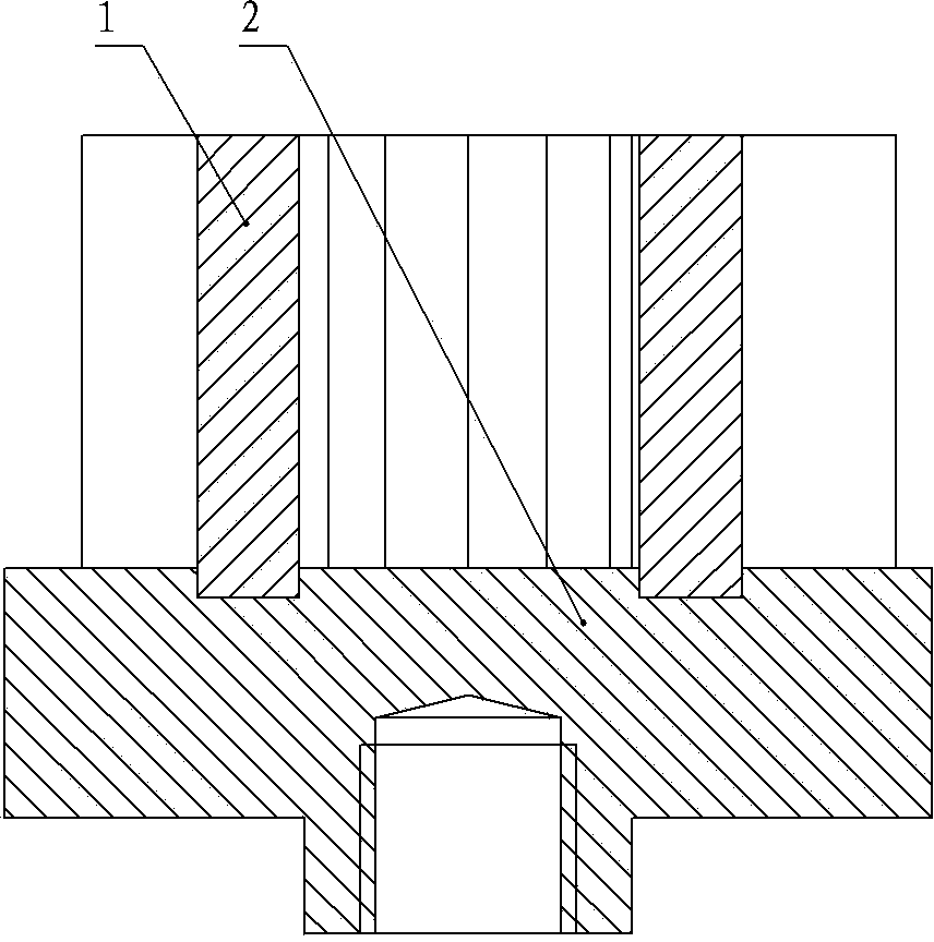
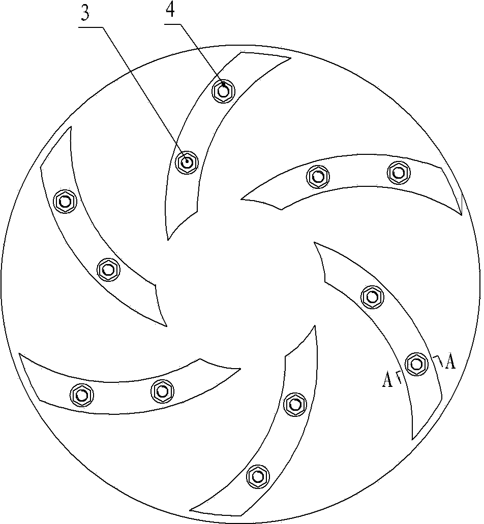
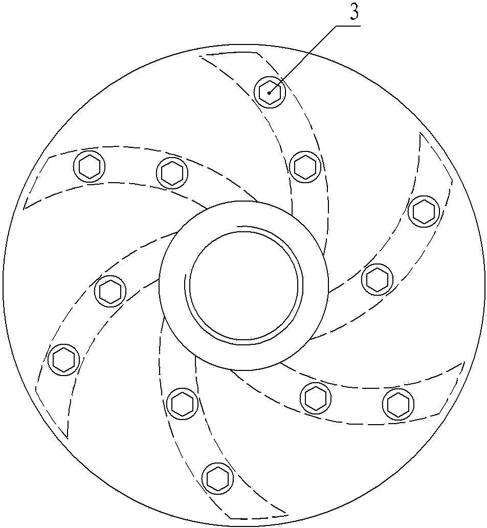
[0029] Embodiment one: if Figure 1~3 The centrifugal pump shown in the figure includes an impeller, which is composed of a blade 1 and a rear cover 2; an installation groove for installing the blade 1 is provided on the end face of the rear cover 2 connected to the blade 1; the bottom of the installation groove is provided with Several through holes, the blade 1 is provided with the connection through hole corresponding to the through hole of the installation groove; There is a countersunk screw hole coaxial with the connection hole of the blade 1; the rear cover 2 is fastened to the blade 1 by bolts 3 and nuts 4 to form an impeller, such as Figure 4 shown.

[0030] The rear cover 2 is made of a wear-resistant material with a hardness greater than or equal to HRC50, and the wear-resistant material is a ceramic material;

[0031] The blade 1 is made of a wear-resistant material with a hardness greater than or equal to HRC50, and the wear-resistant material is a ceramic mate...

Embodiment 2

[0032] Embodiment two: if Figure 1~4 The shown centrifugal pump includes an impeller, the impeller is composed of a blade 1 and a rear cover 2, the structure of the impeller is the same as that of the first embodiment; the rear cover 2 is made of a wear-resistant material with a hardness greater than or equal to HRC50, and the wear-resistant material is a ceramic material ; The surface of the blade 1 is inlaid with a wear-resistant material with a hardness greater than or equal to HRC50, and the wear-resistant material is a ceramic material.

Embodiment 3

[0033] Embodiment three: as Figure 1~4 The shown centrifugal pump includes an impeller, the impeller is composed of a blade 1 and a rear cover 2, the structure of the impeller is the same as that of the first embodiment; the rear cover 2 is made of a wear-resistant material with a hardness greater than or equal to HRC50, and the wear-resistant material is a ceramic material ; The surface of the blade 1 is inlaid with a wear-resistant material with a hardness greater than or equal to HRC50, and the wear-resistant material is hard alloy.


PUM


Abstract

The invention discloses a centrifugal pump, and relates to the technical field of radial flow pump manufacturing. The centrifugal pump comprises an impeller. The impeller is formed by blades and a rear cover plate or formed by blades and a front cover plate, and the blades are connected with the rear cover plate or the front cover plate through connecting pieces. The centrifugal pump can solve the problems that the impeller is short in service life and high in manufacturing and maintenance cost due to the fact that the blades and the cover plates cannot be split in the prior art.

Description

technical field [0001] The invention relates to the technical field of radial flow pump manufacture, in particular to a centrifugal pump whose impeller can be detached into blades and cover plates. Background technique [0002] At present, it is widely used in mining, metallurgy, electric power, chemical industry and other industries to produce centrifugal pumps for slag discharge, ore discharge, and sand excavation (usually called slurry pumps or slurry pumps). The impellers generally adopt two types of structures: semi-open and closed. Form, no matter which structural form is adopted, the blades of the impeller and the rear cover are integrated into one during manufacture; when the centrifugal pump is transporting the mixed fluid of solid and liquid, the blades of the impeller of the centrifugal pump will be broken after working for a period of time. Wear and tear will affect the working performance and service life of the centrifugal pump. In severe cases, the impeller wi...

Claims


Application Information

Patent Timeline
Patent Type & Authority Applications(China)
IPC IPC(8): F04D29/22F04D29/02
Inventor 韦成勋
Owner 柳州市双铠工业技术有限公司
Why Eureka
Try Eureka