Ball valve

A technology for ball valves and valve bodies, which is applied in the direction of valve devices, cocks including cut-off devices, engine components, etc., which can solve the problems of reduced sealing effect and achieve the effect of ensuring sealing reliability

Active Publication Date: 2014-01-15
NEWAY VALVE SUZHOU
View PDF3 Cites 3 Cited by
  • Summary
  • Abstract
  • Description
  • Claims
  • Application Information

AI Technical Summary

Problems solved by technology

[0005] For this reason, the technical problem to be solved by the present invention is the problem that the sealing effect is reduced due to the back and forth movement of the seal on the retaine

Method used


Image

  • Ball valve
  • Ball valve
  • Ball valve

Examples


Embodiment 1

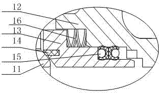
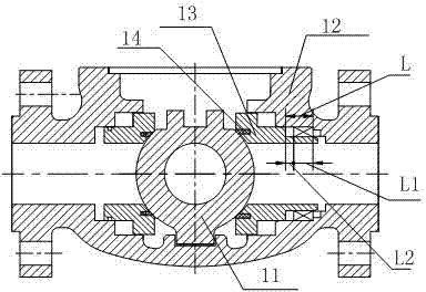
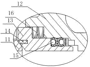
[0027] This embodiment provides a specific structure of the ball valve disclosed in the present invention, such as Figure 5 As shown, it includes a retainer 53 between the valve ball 51 and the valve body 52, a first seal 54 and a second seal 55 are provided between the retainer 53 and the valve body 52, and the first seal 54 is close to the retainer 53, the second seal 55 is set close to the valve body 52, and the valve body 52 and the holder 53 are respectively provided with valves for preventing the first seal 54 from moving to the valve body 52 and the second seal 55 from moving to the holder 53. Barrier 56 .

[0028]The technical solution above is the core technical solution of the present invention. When the left side of the ball valve is pressurized for the first time, the first sealing member 54 moves to the right under the pressure and is blocked by the blocking part 56 on the valve body and does not move again. , and realize the sealing between the retainer 53 and ...

Embodiment 2

[0034] The structure of this embodiment is basically the same as that of Embodiment 1, the difference is:

[0035] In this embodiment, the positions of the first shoulder 561 and the second shoulder 562 are facing each other, and the contact surface between the first stopper 57 and the second stopper 58 is a plane to ensure the contact between the first stopper and the second stopper. Face to face contact is sufficient. This structure can reduce the processing cost of the first stopper 57 and the second stopper 58 .


PUM


Abstract

The invention relates to a ball valve which comprises a fixator positioned between a valve ball and a valve body, wherein a first sealing part and a second sealing part are arranged between the fixator and the valve body; the first sealing part is arranged near the fixator; the second sealing part is arranged near the valve body; baffle parts for blocking the first sealing part from moving to the valve body and blocking the second sealing part from moving to the fixator are respectively arranged on the valve body and the fixator. When the inner left side of the ball valve is pressed for the first time, the first sealing part moves rightwards, is blocked by the baffle part on the valve body, and cannot move, the sealing of the fixator and the valve body is realized, and the left side pressure cannot enable the second sealing part to move; When the inner right side of the ball valve is pressed for the first time, the second sealing part moves leftwards, is blocked by the baffle part on the fixator, and cannot move, the sealing of the fixator and the valve body is realized, and the right side pressure cannot enable the first sealing part to move; no matter what the pressure re-entering direction in the ball valve is, the first sealing part and the second sealing part cannot be displaced, and the sealing reliability of the sealing parts is ensured.

Description

technical field [0001] The invention relates to the technical field of valve production, in particular to a ball valve. Background technique [0002] Ball valve has become one of the most widely used valves due to its reliable sealing, simple structure and convenient maintenance. Among ball valves, DBB and DIB are two types of valve seat functions. Among them, DBB valve seat is also called single-piston effect valve seat. Each valve seat can resist the force in one direction and discharge the middle cavity. DIB valve seat is divided into DIB-1 valve seat and DIB-2 valve seat. Each valve seat of DIB-1 valve seat resists two directions of force, which is called double piston effect valve seat, but this structure needs to be provided with a middle cavity Pressure relief device; DIB-2 The valve seat at the inlet end is DBB, and the outlet end is DIB, also known as single or double piston effect valve seat. This structure automatically releases the pressure in the middle cavity ...

Claims


Application Information

Patent Timeline
IPC IPC(8): F16K5/06F16K5/08F16K5/14
CPCF16K5/0689F16K5/201
Inventor 丁城王国军王建华
Owner NEWAY VALVE SUZHOU
Why Eureka
Try Eureka