Reactor pressure container and working method thereof

A technology of pressure vessels and reactors, applied in the field of nuclear power, can solve problems such as unsuitable marine working conditions and overturning, and achieve the effects of convenient welding and daily operation and maintenance, increased operating space, and reduced spacing

Active Publication Date: 2018-07-06
CHINA NUCLEAR POWER TECH RES INST CO LTD +2
View PDF11 Cites 5 Cited by
  • Summary
  • Abstract
  • Description
  • Claims
  • Application Information

AI Technical Summary

Problems solved by technology

For small offshore stacks in the cabin, on the one hand, space limitations must be considered, the height of the pressure vessel should be reduced as much as possible, and it should be arranged compactly with other main equipment; on the other hand, small offshore stacks are affected by waves and may overturn Therefore, the wind load must be considered as a key design factor, while the traditional land-based stack does not have this consideration and is not suitable for marine conditions

Method used


Image

  • Reactor pressure container and working method thereof
  • Reactor pressure container and working method thereof

Examples


Embodiment Construction

[0028] In order to have a clearer understanding of the technical features, objectives and effects of the present invention, the specific embodiments of the present invention will now be described in detail with reference to the accompanying drawings.

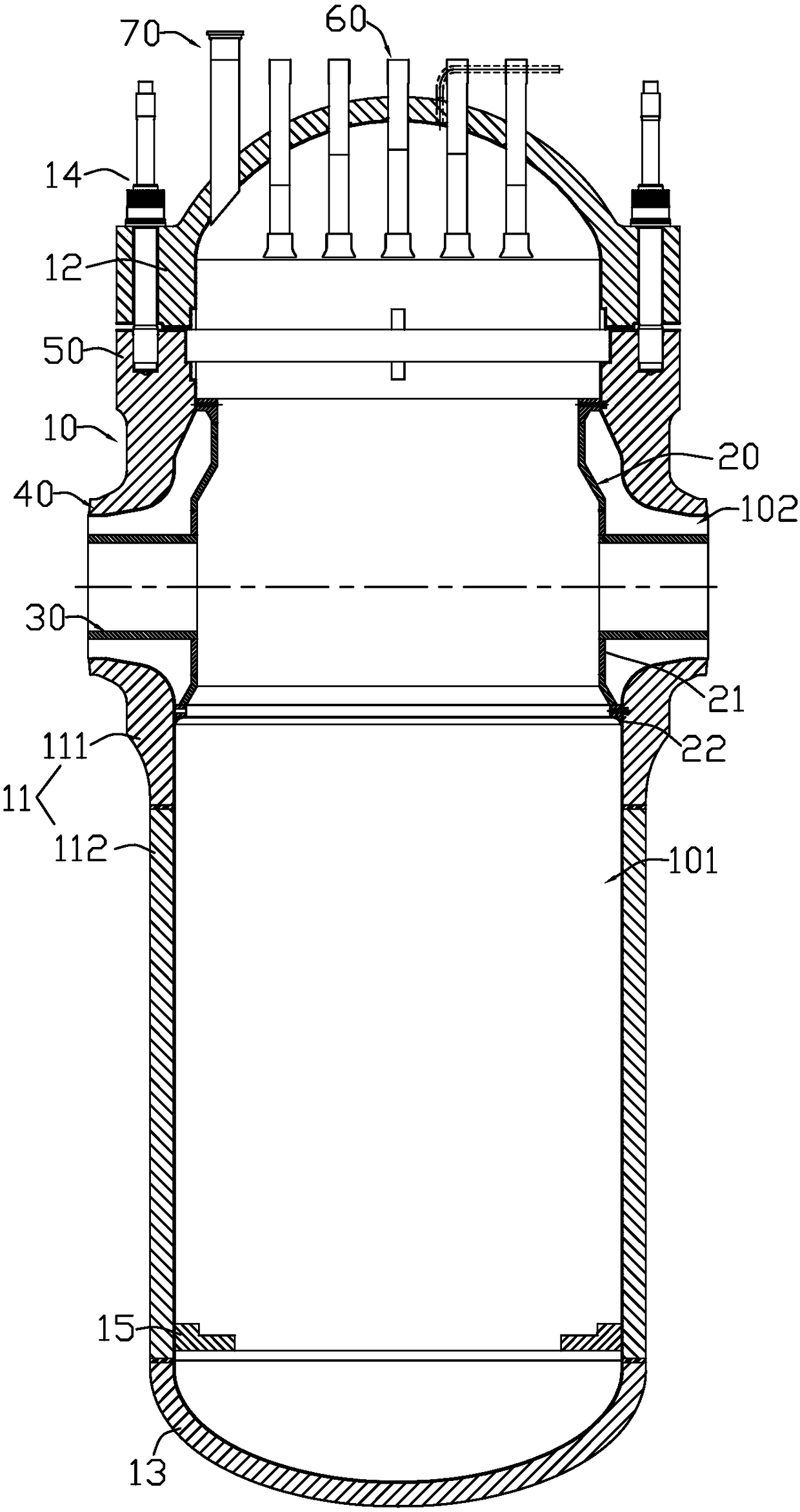
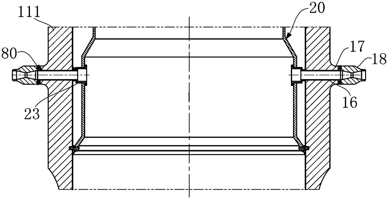
[0029] Such as figure 1 As shown, the reactor pressure vessel according to an embodiment of the present invention includes a sealed vessel body 10, a flow guide ring cavity assembly 20, and at least one internal connecting pipe 30. At least one nozzle 40 is provided on the side of the container body 10, and the guide ring cavity assembly 20 is axially arranged in the container body 10.

[0030] The upper end of the guide ring cavity assembly 20 is located above the nozzle 40 and is connected to the inner wall of the container body 10, and the lower end is located below the nozzle 40 and is connected to the inner wall of the container body 10. The inner connecting pipe 30 is arranged in the connecting nozzle 40, one end is connected t...


PUM


Abstract

The invention discloses a reactor pressure container and a working method thereof. The pressure container comprises a closed container main body, a flow guide ring cavity assembly and at least one inner connecting pipe; at least one filler neck is arranged on the side surface of the container main body; the flow guide ring cavity assembly is axially arranged in the container main body; the upper end of the flow guide ring cavity assembly is positioned above the filler neck and is connected with the inner wall of the container main body; the lower end of the flow guide ring cavity assembly is positioned below the filler neck and is connected with the inner wall of the container main body; the inner connecting pipe is arranged in the filler neck, one end of the inner connecting pipe is connected with the flow guide ring cavity assembly and the other end of the inner connecting pipe corresponds to the pipe orifice of the filler neck; the space among the periphery of the flow guide ring cavity assembly, the periphery of the inner connecting pipe and the inner wall of the corresponding container main body forms a flow guide ring cavity; an internal channel of the inner connecting pipe,an inner channel of the flow guide ring cavity assembly and the internal space of the container main body are communicated to form an internal flow channel; and the internal flow channel is isolated from the flow guide ring cavity. The reactor pressure container meets the compact type arrangement requirement and is suitable for the working condition of the sea.

Description

Technical field [0001] The invention relates to the technical field of nuclear power, in particular to a reactor pressure vessel and a working method thereof. Background technique [0002] Currently, energy supply is becoming increasingly tight. Small reactors are sought after by countries all over the world due to their wide applicability, shorter construction period and lower construction costs. They are vying to develop their own small reactors, especially offshore small reactors. [0003] Traditional land-based high-power reactors are not limited by space. In terms of reactor pressure vessels, the main pipeline structure that has a simple structure but takes up more space can be used to realize the circulation of the primary loop coolant. On the other hand, when small offshore stacks are installed in the cabin, space limitations must be considered, the height of the pressure vessel should be reduced as much as possible, and the compact arrangement with other main equipment; on ...

Claims


Application Information

Patent Timeline
Patent Type & Authority Applications(China)
IPC IPC(8): G21C13/02G21C13/028
CPCG21C13/02G21C13/028Y02E30/30
Inventor 刘强涂盛辉唐叔建韩万富周建明路广遥翟立宏沈黎刘青松芮旻董超群周国丰
Owner CHINA NUCLEAR POWER TECH RES INST CO LTD
Why Eureka
Try Eureka