
LED bulb lamp

A technology of LED bulbs and LED lamp beads, applied in lighting devices, light sources, electric light sources, etc., can solve the problems of increasing light loss, limited area of ​​LEDs, and high light loss, etc. , the effect of wide light angle

Inactive Publication Date: 2014-01-15
广州年创电子有限公司
View PDF6 Cites 2 Cited by
  • Summary
  • Abstract
  • Description
  • Claims
  • Application Information

AI Technical Summary

Problems solved by technology

[0003]However, the lighting angle of the first setting method is limited. Although it can increase some lighting angles, it still cannot meet the required lighting shape and visual effects in many lighting applications. ;In the second setting method, the LED lamp beads are arranged in the lampshade. In order to obtain multi-sided light emission, the LED light-emitting module also needs to be installed on multiple sides. The assembly cost and defect rate increase; in the third setting method, the light guide rod cover is set on the LED lamp bead, and most of the light emitted by the LED must first pass through the light guide rod, and then pass through the light guide rod to emit light. The light loss of the light guide rod There are many, and the diameter of the general light guide column cannot be enlarged due to the loss factor, because the LED emits light in the cross-section of the diameter, uploads to the light guide column, and then refracts and emits light along the vertical axis of the axis, and some of the light passes parallel to the axis. For transparent light, if the diameter is increased, the light loss will be greatly increased. Due to the limited cross-sectional area, the area where LEDs can be placed is also limited, so it is difficult to make bulb lamps with larger wattages. Generally, they are only used in small wattages. 3-5W bulb or candle bulb

Method used


Image

  • LED bulb lamp
  • LED bulb lamp
  • LED bulb lamp

Examples


Embodiment 1

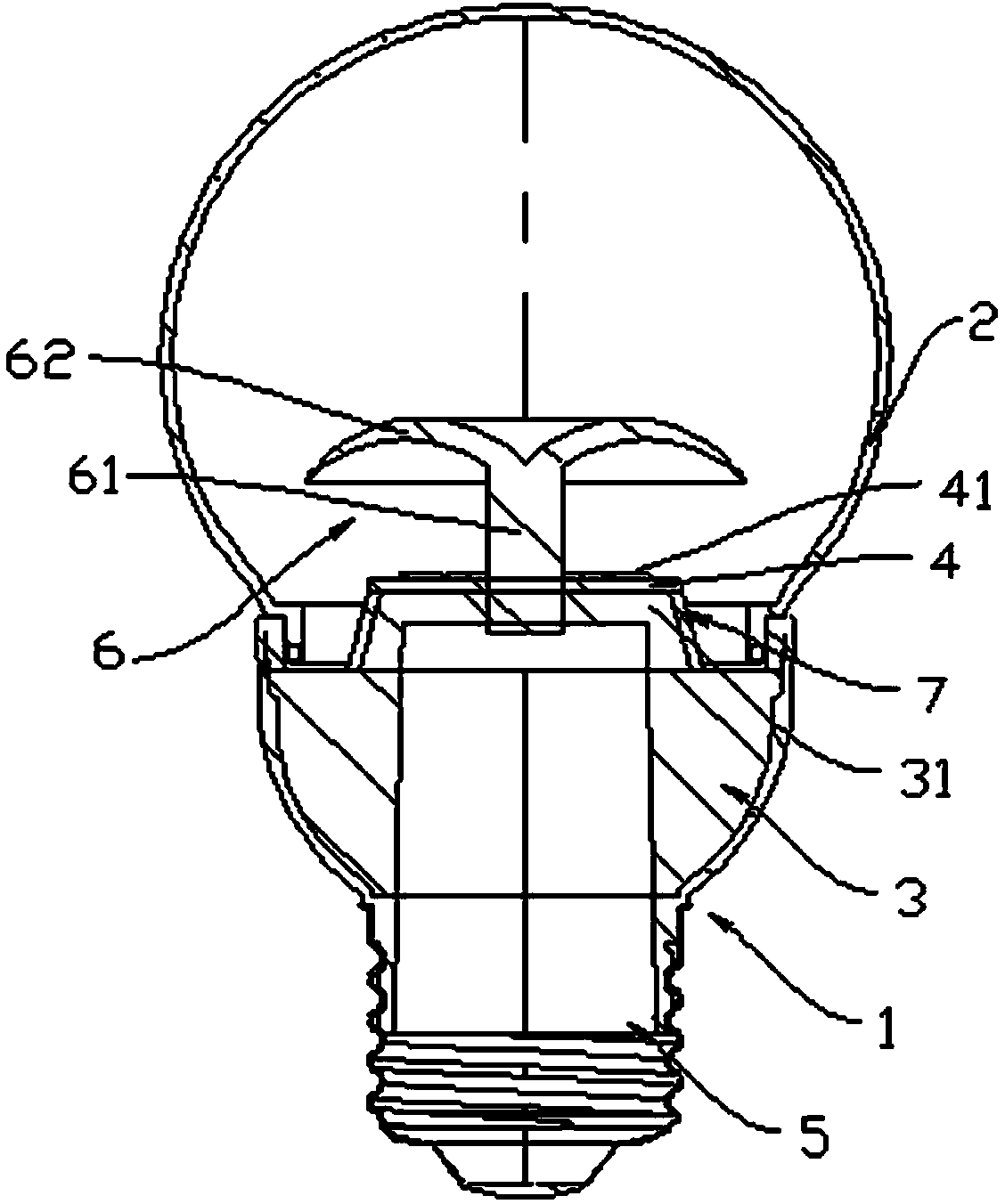
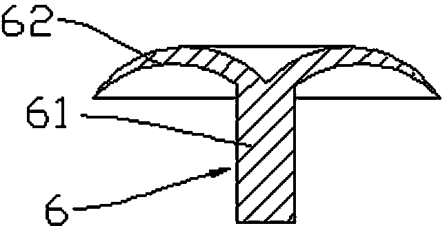
[0037] Refer to attached figure 1 , attached figure 2 As shown, an LED bulb lamp includes a lamp holder 1, a lampshade 2, a substrate 4, an integrated and packaged LED lamp bead 41 and a driving power supply 5, and the LED lamp bead 41 is arranged on the substrate 4 and connected to the The driving power supply 5 is electrically connected, the substrate 4 is fixed on the lamp holder 1 and arranged inside the lampshade 2, the lampshade 2 is connected to the lamp holder 1 and fixed on the lamp holder 1, and it also It includes a light distribution member 6, the light distribution member 6 includes a support portion 61 installed on the lamp holder 1, and a light distribution portion 62 extending radially outward from the circumferential direction of the support portion 61. The light distribution part 62 is located inside the lampshade 2 and disposed above the LED lamp bead 41 , and the projection of the light distribution part 62 on the substrate 4 covers the projection of ...

Embodiment 2

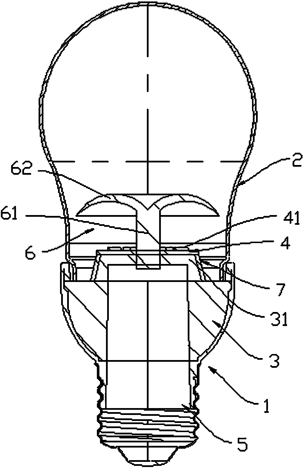
[0050] Refer to attached image 3 As shown, the lampshade 2 includes a substantially hemispherical upper part and a lower part connected to the lamp holder 1, and other settings are the same as in the first embodiment, and the visual effect formed by the emitted light is different from that of the first embodiment.

Embodiment 3

[0052] Refer to attached Figure 4 As shown, the shape of the lampshade 2 is roughly cylindrical, and other arrangements are the same as in the first embodiment, but the visual effect formed by the emitted light is different from the first and second embodiments.


PUM


Abstract

The invention relates to an LED bulb lamp. The LED bulb lamp comprises a lamp holder, a lampshade, a substrate, integrally-encapsulated LED lamp beads and a drive power supply, wherein the LED lamp beads are arranged on the substrate and electrically connected with the drive power supply, the substrate is fixed on the lamp holder and arranged inside the lampshade, and the lampshade is connected with the lamp holder and fixed on the lamp holder. The LED bulb lamp further comprises a light distribution member, wherein the light distribution member comprises a supporting portion installed on the lamp holder and a light distribution portion. The periphery of the supporting portion outward extends in the radial direction to form the light distribution portion, the light distribution portion is located inside the lampshade and arranged above the integrally-encapsulated LED lamp beads, and at least one part of axial projection of the light distribution portion on the substrate covers the LED lamp beads. An irritation angle and an illumination light pattern of the LED bulb lamp are increased, and the visual effect of the illumination is good.

Description

technical field [0001] The invention relates to an LED bulb lamp. Background technique [0002] LED bulbs use LED as the light source. Due to the large brightness of LED and the concentration of direct light intensity, it is more dazzling; and the light angle is small, generally 180 degrees. The light angle that can be obtained is limited and does not meet the vision of lighting applications. Effect. Therefore, at present, in order to increase the luminous angle, combined with the application occasion of the LED bulb lamp and the desired lighting shape and visual effect, there are mainly the following three design methods in the prior art: 1. Change the shape, haze and material of the lampshade ; 2. Vertically arrange the substrate attached with LED lamp beads in the lampshade; 3. Set a light guide column on the LED lamp beads. [0003] However, the luminous angle of the first setting method is limited. Although it can increase some luminous angles, it still cannot meet th...

Claims


Application Information

Patent Timeline
Patent Type & Authority Applications(China)
IPC IPC(8): F21S2/00F21V13/04F21Y101/02F21K9/232F21K9/237F21K9/65F21Y115/10
Inventor 萧标颖
Owner 广州年创电子有限公司
Learn More