Electronic device and method for adjusting working mode of electronic device

A technology of electronic devices and working modes, applied in measuring devices, data processing power supplies, measuring flow/mass flow, etc., can solve problems such as waste of resources, affecting charging speed, low output power of radio frequency signals, etc., and achieve the effect of improving performance

Active Publication Date: 2016-04-20
AMBIT MICROSYSTEMS (SHANGHAI) LTD
View PDF5 Cites 0 Cited by
  • Summary
  • Abstract
  • Description
  • Claims
  • Application Information

AI Technical Summary

Problems solved by technology

When designing and producing electronic products, the standard specifications of USB must be considered, and the power when charging or supplying power to the USB interface is limited to the standard USB output power. For example, the power used by wireless routing products is limited to 2.5W. Below, or limit the charging power of mobile phones, digital cameras, etc. through the USB power supply to less than 2.5W. However, when the wireless routing products are limited to less than 2.5W, the output power of the RF signal is relatively low, which limits the data transmission speed and signal coverage. range, and when the charging power of mobile phones, digital cameras, etc. is limited to 2.5W, it will obviously affect the charging speed
Therefore, in the prior art, even if the USB power supply can provide a power output power of 5W (5V / 1A), due to the limitation of the electronic device itself, the power output power cannot be used, resulting in a waste of resources

Method used


Image

  • Electronic device and method for adjusting working mode of electronic device
  • Electronic device and method for adjusting working mode of electronic device
  • Electronic device and method for adjusting working mode of electronic device

Examples


Embodiment Construction

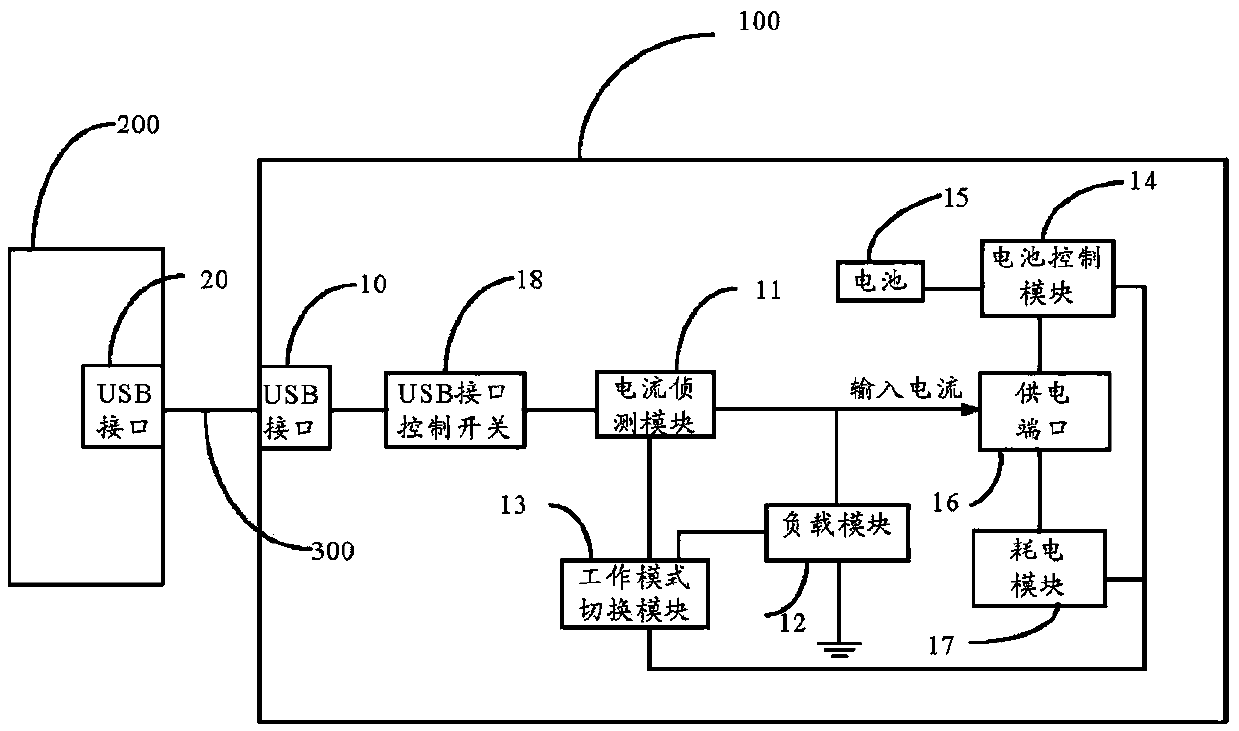
[0021] see figure 1 , is a functional block diagram of an electronic device according to an embodiment of the present invention. The electronic device 100 includes a USB interface 10, a current detection module 11, a load module 12, an operating mode switching module 13, a battery control module 14, a battery 15, a power supply port 16 and Power consumption module 17. The USB interface 10 of the electronic device 100 is used to connect to the USB interface 20 of an external device 200 through a USB connection cable 300 and obtain current from the USB interface 20 of the external device 200 . The current detection module 11 is used for detecting the output current of the USB interface 20 of the external device 200 . The load module 12 is electrically connected between the USB interface 10 and ground. The working mode switching module 13 is connected with the current detection module 11 and the load module 12, and is used to gradually control and reduce the load size of the lo...


PUM


Abstract

The invention relates to an electronic device. The electronic device comprises a USB interface, a current detection module, a load module, a work mode switching module, a power supply port and a power consumption module. The power supply port is used for outputting working currents to the power consumption module. The electronic device is connected with a USB interface of an external device through the USB interface to obtain currents. Output currents of the USB interface of the external device are detected by the current detection module. The work mode switching module controls output currents of the USB interface of the external device to constantly increase by constantly controlling and reducing the load value of the load module and determines the maximum power supply power which the USB interface of the external device can provide when the work mode switching module judges that the output currents detected by the current detection module do not increase any more. In addition, the work mode switching module adjusts the work modes of the electronic device according to the maximum power. The electronic device can adjust the work modes according to the power which the USB power supply can provide, and thus the efficacy of the electronic device is improved. The invention further provides a method for adjusting the work modes of the electronic device.

Description

technical field [0001] The present invention relates to an electronic device, in particular to an electronic device and method capable of adjusting the working mode based on the output power of a power supply. Background technique [0002] At present, some electronic devices, such as wireless routing equipment (such as MIFI, USBWI-FIAP products, etc.), mobile phones, digital cameras, e-books, etc., when connected to the USB interface, the input power is a standard USB power supply, and the standard USB interface The output power specification is 2.5W (5V / 500mA), but some USB power supplies on the market can provide up to 5W (5V / 1A) power output power. When designing and producing electronic products, it is necessary to consider the standard specifications of USB, and the power when charging or supplying power to the USB interface is limited to the standard USB output power. For example, the power of wireless routing products is limited to 2.5W. Below, or limit the charging ...

Claims


Application Information

Patent Timeline
Patent Type & Authority Patents(China)
IPC IPC(8): G06F1/26
Inventor 游舜良
Owner AMBIT MICROSYSTEMS (SHANGHAI) LTD
Why Eureka
Try Eureka