Photoelectric composite cable

A photoelectric composite cable and cable core technology, which is applied in the direction of communication cables, cables, circuits, etc., can solve the problems of difficult installation and single function, and achieve the effects of increasing installation speed, reducing friction, and avoiding repeated wiring

Inactive Publication Date: 2014-01-15
成都亨通光通信有限公司
View PDF0 Cites 2 Cited by
  • Summary
  • Abstract
  • Description
  • Claims
  • Application Information

AI Technical Summary

Problems solved by technology

[0004] The purpose of the present invention is to overcome the deficiencies of the current technology and provide a photoelectric composite cable to solve the following problems: (1) The existing air-feed optical cable is difficult to install because of excessive friction with the installation pipe; (2) Some optical cables can only provide broadband access, and the role is too single

Method used


Image

  • Photoelectric composite cable

Examples


Embodiment Construction

[0014] Below in conjunction with embodiment the present invention is described in further detail, but structure of the present invention is not limited to following embodiment:

[0015] 【Example】

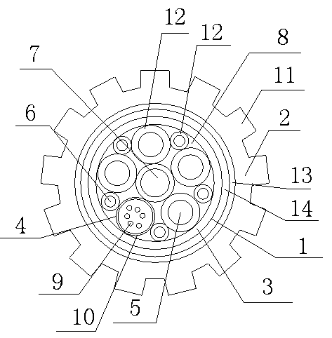
[0016] like figure 1 As shown, the photoelectric composite cable includes a cable core 1 and an outer sheath 2 wrapping the cable core 1. The cable core 1 includes a wrapping layer 3, and the wrapping layer 3 is provided with an optical fiber unit 4 and a signal line copper conductor. 5. The power supply copper conductor 6 and the central strengthening member 7, the central strengthening member 7 is located at the center of the wrapping layer 3, the optical fiber unit 4, the signal line copper conductor 5, and the power supply copper conductor 6 are arranged around the central strengthening member 7, and the optical fiber unit 4 , the signal line copper conductor 5, the power supply copper conductor 6 and the central strength member 7 are all fixed in the wrapping layer 3 by ointme...


PUM


Abstract

The invention discloses a photoelectric composite cable. The photoelectric composite cable comprises a cable core (1) and an outer protection sleeve (2) coating the cable core (1), the cable core (1) comprises a binding layer (3), an optical fiber unit (4), signal line copper conductors (5), power supply copper conductors (6) and a central reinforcer (7) are arranged inside the binding layer (3), protruding grains (11) are arranged on the periphery of the protection sleeve (2), and the cross section of the protruding grains (11) is square. The photoelectric composite cable has the advantages that the protruding grains are arranged on the surface of the optical cable, the friction between the optical cable and a mounting pipe is reduced, and mounting speed is obviously improved; a power supply line and a signal line are arranged in the photoelectric composite cable, the problems of equipment broadband access, equipment power utilization and signal transmission are simultaneously solved, and repeated wiring is avoided.

Description

technical field [0001] The invention relates to a photoelectric composite cable. Background technique [0002] Optical cables are mainly composed of optical fibers (glass filaments as thin as hair), plastic protective sleeves and plastic sheaths. Optical cable is the main transmission tool of various information networks in today's information society. [0003] Existing optical cables only provide a single broadband access, and additional wiring is required for power supply and signal transmission of equipment, making the wiring very complicated; many optical cables are installed through pipelines, that is, the protective tube is first set up, and then the optical cable is blown into the protective tube. However, the existing optical cables often have too much friction between the cable sheath and the protective tube, which makes installation difficult and sometimes even causes damage to the optical cable. Contents of the invention [0004] The purpose of the present inv...

Claims


Application Information

Patent Timeline
Patent Type & Authority Applications(China)
IPC IPC(8): H01B11/22
Inventor 孙义兴何吉焱许建国陈曲刘东陈治均
Owner 成都亨通光通信有限公司
Why Eureka
Try Eureka