LED constant-current driver with boost function

A constant current driver and driver technology, applied in energy-saving control technology, lighting devices, light sources, etc., can solve problems such as insignificant overvoltage protection of fuses

Inactive Publication Date: 2014-01-15
JIANGSU SMILE OPTOELECTRONICS TECH
View PDF0 Cites 0 Cited by
  • Summary
  • Abstract
  • Description
  • Claims
  • Application Information

AI Technical Summary

Problems solved by technology

Second, most of the controller output protection in the market currently adopts the method of fuse. This method has a certain protection delay due to the fuse, and the fuse is not obvious for overvoltage protection.

Method used


Image

  • LED constant-current driver with boost function

Examples


Embodiment Construction

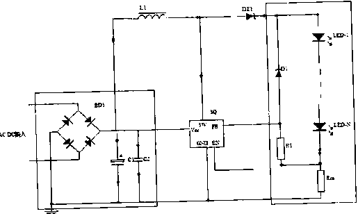
[0011] LED constant current driver with boost function, the driver includes a voltage stabilizing circuit connected between the power supply and the load, a boost control circuit, a voltage conversion circuit and a constant current control circuit, the power supply, voltage stabilizing circuit, boost The voltage control circuit, the voltage conversion circuit, the constant current control circuit and the load are connected in sequence, the voltage stabilizing circuit includes a rectifier bridge, capacitors C1 and C2, the capacitor C1 or C2 is connected to the power input terminal, and the inductance L is connected to the input terminal , the other end of the inductor L is connected to the SQ chip, and at the same time connected to the DZ1 fast recovery diode, the other end of the DZ1 fast recovery diode is connected to the output end; the diode D1, the resistors R1 and Rcs are respectively connected to the output end.

[0012] When the present invention works, the output end of...


PUM


Abstract

The invention relates to an LED constant-current driver with a boost function. The driver comprises a voltage stabilizing circuit connected between a power supply and a load, a boost control circuit, a voltage conversion circuit and a constant-current control circuit. The power supply, the voltage stabilizing circuit, the boost control circuit, the voltage conversion circuit, the constant-current control circuit and the load are connected in order. According to the invention, expectant brightness requirement can be met; consistency in brightness and chroma of each LED can be guaranteed; there is no input polarity; that driving output voltage and current exceed the maximum value to affect reliability of the driver is avoided; and input voltage can be stepped up to a required voltage.

Description

technical field [0001] The invention relates to a constant current driver, in particular to an LED constant current driver with boost function. Background technique [0002] The current constant current on the market strictly distinguishes the positive and negative plates of the input terminal. If the positive and negative poles are reversed during the construction process, the constant current drive will be damaged. Second, most of the controller output protection in the market currently adopts the method of fuse. This method has a certain protection delay due to the fuse, and the fuse is not obvious for overvoltage protection. Contents of the invention [0003] The purpose of the present invention is to provide a LED that can meet the expected brightness requirements, and ensure the consistency of the brightness and chromaticity of each LED. It has no input polarity and can avoid driving output voltage and current exceeding the maximum value, thereby affecting its reliab...

Claims


Application Information

Patent Timeline
Patent Type & Authority Applications(China)
IPC IPC(8): H05B37/02
CPCY02B20/40
Inventor 夏平中雍冬梅
Owner JIANGSU SMILE OPTOELECTRONICS TECH
Why Eureka
Try Eureka