Lauter tun

A filter barrel and guide rod technology, which is applied in the field of filter barrels to achieve optimized results, low flow resistance, and improved loosening effect.

Inactive Publication Date: 2015-04-29
KRONES AG
View PDF14 Cites 0 Cited by
  • Summary
  • Abstract
  • Description
  • Claims
  • Application Information

AI Technical Summary

Problems solved by technology

Another disadvantage of this configuration is that, over the entire cross-section of the spent grains bed, no continuous horizontal porosity zone is formed that constantly affects the flow rate of the liquid phase through the spent grains bed

Method used


Image

  • Lauter tun
  • Lauter tun
  • Lauter tun

Examples


Embodiment Construction

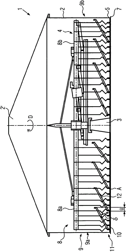
[0028] figure 1 The height shows a schematic view of a longitudinal section of the lauter tun 1 . The lauter tun 1 comprises: a generally cylindrical housing 2 for containing malt pulp; and a drive shaft 3 arranged on a vertical centerline 2' of the lauter tun 1 around which rake means 4 are driven. 'Turn. Furthermore, during operation, the rake device 4 can be adjusted up and down by a lifting device not shown.

[0029] The housing 2 comprises a so-called false bottom 5, which is arranged at a certain distance above a collection chamber 7, in which the liquid phase containing refined juice (filtered wort) discharged from the malt pulp and washed with jet water is collected , for further beer making and can be withdrawn.

[0030] The rake device 4 generally comprises at least one (preferably several) rake arms 8, of which only two rake arms 8a and 8b diametrically opposite with respect to the center line 2' are shown here. The rake arms 8a, 8b are arranged above the maximu...


PUM

PropertyMeasurementUnit
lengthaaaaaaaaaa

Abstract

A lauter tun is described having a chopping device which has at least one chopping tool that is moveable for generating a substantially vertical cut through a spent grain bed deposited on a bottom of the lauter tun. The lauter tun additionally contains a loosening appliance which is moveable substantially horizontally through the spent grain bed. In order to improve the lautering performance, it is proposed to seal the loosening appliance by the end of the chopping tool that is close to the bottom or to arrange the loosening appliance at a distance above the end of the chopping tool that is close to the bottom and provide it with at least one spent grain guide strip, the cross-sectional shape of which in the rim region that is at the rear with respect to the direction of motion of the chopping tool is directed upwards.

Description

technical field [0001] The invention relates to a lauter tun with a rake device of the type described in the preamble to variant 1 . Background technique [0002] Such a lauter tun is known from DE637376. The lauter tun is used for the solid-liquid separation of the mash, where the solid components (spent grains) are separated from the mash and fed to other applications. The liquid phase (wort) is separated in the process and then boiled in a wort kettle with the addition of hops. The filtration treatment is preferably carried out in two steps. In a first step, the first wort is drained, i.e. the malt located in the lauter tun is allowed to be drained in a state where the solid components (such as grain husks) serve as a filter layer after settling in the false bottom of the lauter tun Slurry liquid in which a live bottom keeps the turbidity separate from the liquid phase. The aim is to obtain a preferably refined wort free of solids. Then, in order to leave as little e...

Claims


Application Information

Patent Timeline
Patent Type & Authority Patents(China)
IPC IPC(8): C12C7/17
CPCC12C7/17
Inventor R·格鲁伯M·武姆J·罗福莱德
Owner KRONES AG
Why Eureka
Try Eureka