
Beam-limiting device blade driving device, beam-limiting device and X-ray machine

A driving device and beam limiter technology, which is applied in the field of beam limiter and X-ray machine, can solve the problems affecting the precision of blade movement, complex gear processing, high cost, etc., and achieve the effect of easy disassembly and replacement, easy maintenance and simple structure

Active Publication Date: 2015-04-22
ZHUHAI INST OF ADVANCED TECH
View PDF8 Cites 0 Cited by
  • Summary
  • Abstract
  • Description
  • Claims
  • Application Information

AI Technical Summary

Problems solved by technology

[0009] The above-mentioned beam limiter blade driving device has a relatively complicated structure, many parts, and relatively high cost
In the gear pendulum drive device, the gear processing is more complicated, the assembly adjustment is more difficult, and the gap between the gears will affect the precision of the blade movement; in the wire rope pendulum drive device, although the parts are easier to process, the blade opening and closing degree and the knob rotation The angle is a non-linear relationship, so the scale can only be non-linear. At the same time, the left and right blades and the front and rear blades move in a circular arc due to the swing rod, and the vertical distance is relatively large. Even if the blades are completely closed, there is a risk of radiation leakage; In the wire rope linear guide rail drive device, a large number of reversing wheels are required, which takes up a lot of space, and the cost of the linear guide rail is relatively high; in the screw linear guide rail drive device, the cost of the screw rod and linear guide rail is very high, and assembly adjustment It is more difficult; in the cam swing rod driving device, the machining of the cam groove on the cam is relatively complicated, and the machining accuracy is relatively high. At the same time, because the swing rod moves in a circular arc, the upper and lower distances are relatively large, and there is also the risk of radiation leakage.

Method used


Image

  • Beam-limiting device blade driving device, beam-limiting device and X-ray machine
  • Beam-limiting device blade driving device, beam-limiting device and X-ray machine
  • Beam-limiting device blade driving device, beam-limiting device and X-ray machine

Examples


Embodiment 1

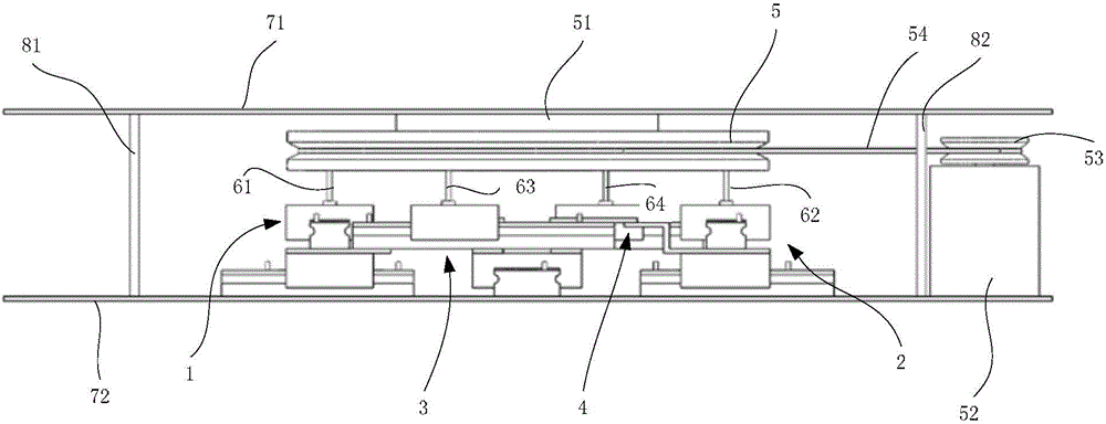
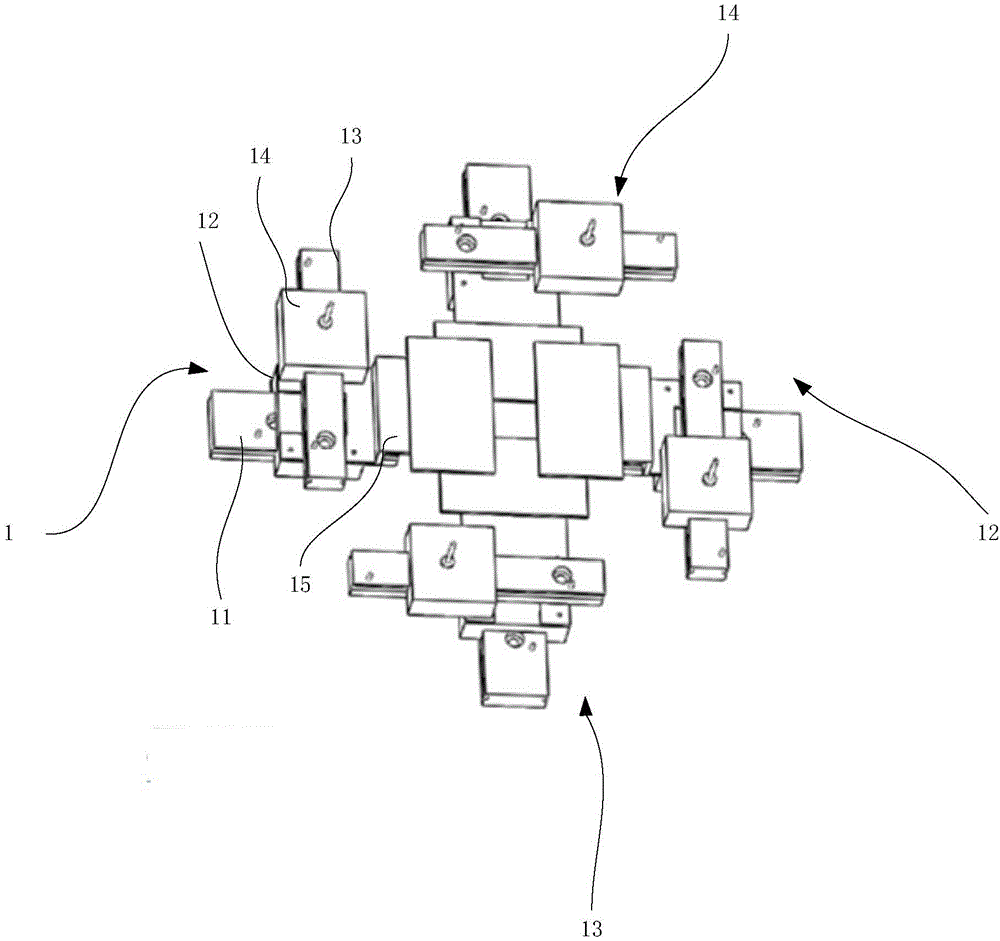
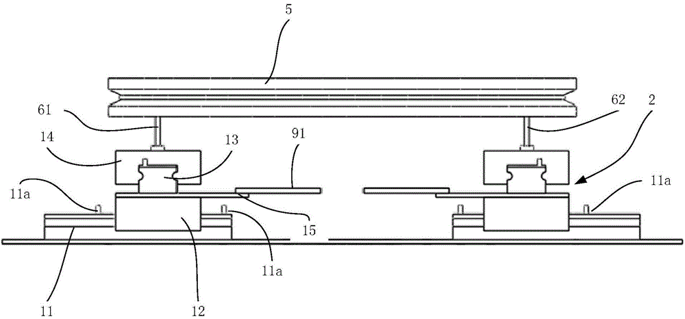
[0051] Embodiment 1 of the present invention provides a beam limiter blade driving device, which is used to drive the blades of the beam limiter, such as figure 1 As shown, the device includes: an upper plate 71, a lower plate 72, a rotating wheel 5, four pin shafts, and four blade fixing transmission mechanisms, wherein the rotating wheel 5 is horizontally arranged below the upper plate 71 and fixed by a flange 51 On the lower surface of the upper plate 71, four pin holes are arranged symmetrically in the center of the rotating wheel 5; the four pin shafts are respectively installed in the above pin holes and vertically arranged, and the four pin shafts are respectively the first pin shaft 61, The second pin shaft 62, the third pin shaft 63 and the fourth pin shaft 64; the four blade fixed transmission mechanisms are respectively the first blade fixed transmission mechanism 1, the second blade fixed transmission mechanism 2, the third blade fixed transmission mechanism 3 and ...

Embodiment 2

[0058] Embodiment 2 of the present invention provides a beam limiter, such as Figure 4 As shown, the limiter includes: a housing 10 for shielding rays, a bulb 20, a flange connection mechanism 30, four blades and the beam limiter blade driving device 40 of Embodiment 1, wherein the bulb 20 passes through the method The blue connection mechanism 30 is arranged on the upper part of the casing 10, and the beam limiter blade driving device 40 is arranged under the bulb 20. For the beam limiter blade driving device 40, please refer to Embodiment 1, and details will not be repeated here.

[0059] The four blades are respectively arranged on the four connecting plates of the beam limiter blade driving device 40 .

[0060] The blades in this embodiment are arranged in a cross shape.

Embodiment 3

[0062] Embodiment 3 of the present invention provides an X-ray machine, including a beam limiter, wherein the beam limiter includes the beam limiter blade driving device in Embodiment 1. For the beam limiter blade driving device 40, please refer to Embodiment 1 , which will not be detailed here.


PUM


Abstract

The invention relates to the technical field of medical equipment, in particular to a beam-limiting device blade driving device which is used for driving blades of a beam-limiting device. The beam-limiting device blade driving device comprises an upper-layer plate, a lower-layer plate, a rotating wheel, four hinge pins and four blade fixing and transmitting mechanisms, wherein the rotating wheel is horizontally arranged below the upper-layer plate, four pin holes are distributed in the rotating wheel in a central symmetry mode, and the rotating wheel is fixed to the lower surface of the upper-layer plate through a flange; the four hinge pins penetrate through the pin holes respectively and are arranged vertically; the four blade fixing and transmitting mechanisms are arranged at the lower ends of the four hinge pins respectively. The invention further provides the beam-limiting device provided with the beam-limiting device blade driving device and an X-ray machine. The beam-limiting device blade driving device is simple in structure, low in cost and easy to maintain.

Description

【Technical field】 [0001] The invention relates to the technical field of medical equipment, in particular to a blade driving device of a beam limiter, a beam limiter and an X-ray machine provided with the blade driving device. 【Background technique】 [0002] In the X-ray machine system, the beam limiter is usually installed under the tube, and the tube emits X-rays, and the X-rays are projected onto the subject through the blade openings inside the beam limiter. The size of the blade opening of the beam limiter, that is, the opening size of the blades, determines the projection range of the emitted X-rays, and the excess rays emitted by the tube beyond the range of the blade openings will be absorbed and blocked by the blades and cannot be emitted. It is well known that X-rays are harmful to the human body, so it is necessary to control the projection range of X-rays so that they only irradiate the parts that the patient needs to check, so that the parts that the patient doe...

Claims


Application Information

Patent Timeline
Patent Type & Authority Patents(China)
IPC IPC(8): A61B6/00
Inventor 刘勇熊璟李志成谢耀钦陈鸣闽王丽艳陈垦李生广孟书先
Owner ZHUHAI INST OF ADVANCED TECH
Learn More