Multi-beam pulse inversion imaging method and system

An imaging method and multi-beam technology, which is applied in the directions of acoustic wave diagnosis, infrasonic wave diagnosis, ultrasonic/sonic wave/infrasonic wave diagnosis, etc., can solve the problems of complex multi-beam operation and reduced frame frequency of pulse inversion harmonic imaging technology, and reduce complexity Effect

Active Publication Date: 2015-12-09
VINNO TECH (SUZHOU) CO LTD
View PDF10 Cites 0 Cited by
  • Summary
  • Abstract
  • Description
  • Claims
  • Application Information

AI Technical Summary

Problems solved by technology

[0007] The present invention provides a multi-beam pulse inversion imaging method and system, which solves the problems of reduced frame frequency and complicated multi-beam operation in the pulse inversion harmonic imaging technology.
[0008] The present invention also provides a multi-beam pulse inversion imaging method and system under multi-focus, which solves the problems of reduced frame frequency and complicated multi-beam operation of the pulse inversion harmonic imaging technology.
[0009] The present invention further provides a method and system for pulse inversion imaging of different beams under multi-focus, which solves the problems of reduced frame frequency and complex multi-beam operation of pulse inversion harmonic imaging technology.

Method used


Image

  • Multi-beam pulse inversion imaging method and system
  • Multi-beam pulse inversion imaging method and system
  • Multi-beam pulse inversion imaging method and system

Examples


Embodiment 1

[0070] The multi-beam pulse inversion imaging method of the embodiment of the present invention, for the convenience of description, in the embodiment of the present invention, only 3 to 4 emission lines are used to describe the embodiment of the present invention, but it should be noted that the present invention is not limited thereto , it can also be applied to the situation of more emission lines, wherein the application of the number of emission lines can have different settings, and the scope of protection of the claims of the present invention is not limited to the situation of 3 to 4 emission lines, and it also protects more The case of emission lines.

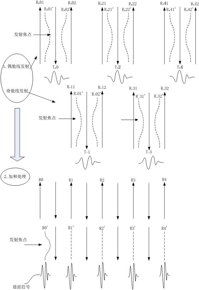
[0071] Embodiment of the present invention a multi-beam pulse inversion imaging method, such as figure 1 shown, including the following steps:

[0072] In step S1, the transmitter divides the transmitted scanning lines into two groups of odd and even, and controls the transmitting lines of one group to emit positive o...

Embodiment 2

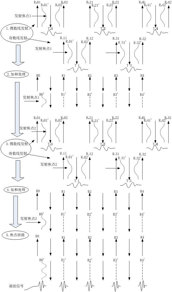
[0094] Based on the same inventive concept as in Embodiment 1, in Embodiment 2 of the present invention, a multi-beam pulse inversion imaging method under multi-focus is provided, including the following steps:

[0095] Step S10, the transmitter divides the transmitted scanning line settings into two groups of odd and even at the i-th transmitting focus, and controls one of the groups to emit positive polarity or negative polarity pulses, and the other group to emit anti-phase pulses;

[0096] Among them, i=1,...,N, N is a positive integer greater than or equal to 2;

[0097]Step S20, after the receiver receives the receiving beam corresponding to the scanning line of the i-th transmitting focus transmitted in step S10, it performs summation processing on the actual receiving beam corresponding to the expected receiving beam whose spatial position overlaps to obtain the i-th transmitting focus harmonic signal;

[0098] Step S30 , performing focus splicing on the harmonic sign...

Embodiment 3

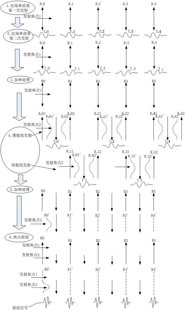
[0123] Based on the same inventive concept as in Embodiment 1 and Embodiment 2, in Embodiment 3 of the present invention, a pulse inversion imaging method of different beams under multi-focus is provided, including the following steps:

[0124] Step S100, the transmitter performs different beam control for different transmission focal points, and configures the number of beams according to the focal points;

[0125] In the third embodiment, in the multi-beam pulse inversion imaging technology of the present invention, in the case of multi-focus, different beam controls are performed on different transmission focuses, and the number of beams is configured according to the focus.

[0126] As an implementable manner, preferably, the configuration of the number of beams according to the focal point refers to the configuration of a single beam in the near field of the transmitter, and the configuration of dual beams or four beams or more beams in the middle and far field of the tran...


PUM


Abstract

The invention discloses a multi-beam pulse reverse imaging method and system. The method comprises the following steps: step 1, an emitter divides emitted scanning lines into an odd group and an even group, and controls the emitted lines in one group to emit positive polarity pulses or negative polarity pulses and the lines in the other group to emit phase reversal pulses; step 2, a receiver conducts addition processing on actually received beams corresponding to beams which are expected to be received and overlapped in spatial position after receiving the beams corresponding to the scanning lines emitted in the step 1 to obtain a harmonic signal. By means of the multi-beam pulse reverse imaging method and system, the purposes of beam distortion correction and harmonic signal acquisition are achieved at the same time, and the flexibility of echo signal processing is lowered.

Description

technical field [0001] The invention relates to the technical field of medical ultrasonic imaging, in particular to a multi-beam pulse inversion imaging method and system. Background technique [0002] Harmonic imaging technology extracts high-order harmonic components in the received signal by transmitting a fundamental wave signal of a certain frequency, and finally forms a harmonic image. In harmonic imaging technology, the front end of the system transmits the fundamental wave signal into human tissue. Due to the nonlinearity of human tissue, the fundamental wave will generate high-order harmonic components during the propagation process, and information related to the nonlinearity of human tissue can be obtained. Since the generation of harmonics in human tissue is the result of energy accumulation, there are fewer harmonic components in the near field of the image, which can reduce artifacts such as reverberation and multiple reflections in the near field. Secondly, t...

Claims


Application Information

Patent Timeline
Patent Type & Authority Patents(China)
IPC IPC(8): A61B8/00
Inventor 吴方刚
Owner VINNO TECH (SUZHOU) CO LTD
Why Eureka
Try Eureka