Automatic water inflowing and draining structure of water bath
A water bath, water inlet and drainage technology, which is applied to contraceptives, heating appliances for therapeutic treatment, cooling appliances for therapeutic treatment, etc., can solve the problems of time-consuming, water overflow in the water bath, laborious and other problems, and avoid excessive or excessive Less, labor-saving effect
- Summary
- Abstract
- Description
- Claims
- Application Information
AI Technical Summary
Problems solved by technology
Method used
Image

Examples
Embodiment 1
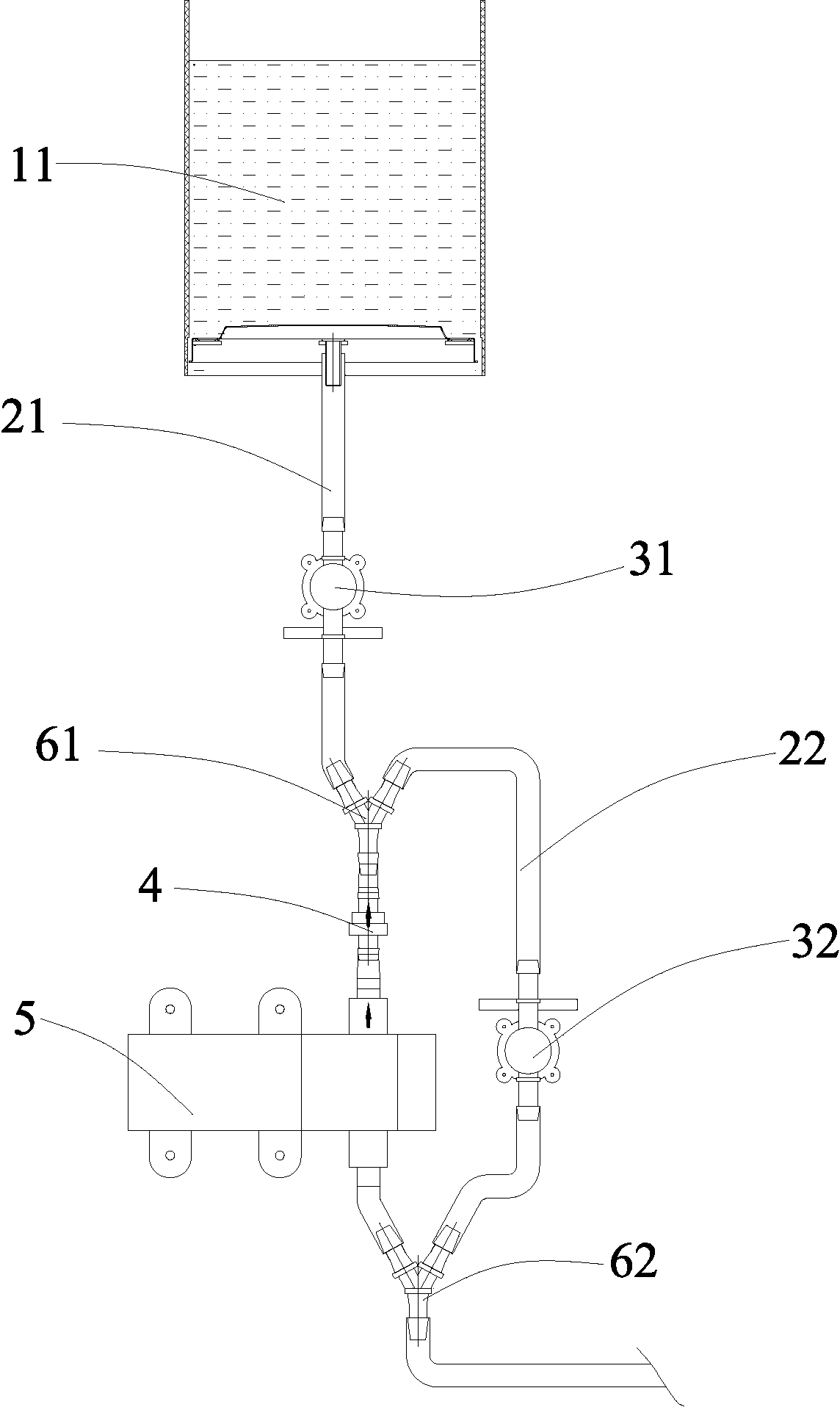
[0012] Such as figure 1 As shown, the automatic water inlet and drainage structure of the water bath includes a water bath tank body 11, a liquid level sensor is installed in the tank body 11, a first pipeline 21 is connected to the bottom of the tank body 11, and the first pipeline 21 is sequentially equipped with The first solenoid valve 31, the one-way valve 4 and the self-priming pump 5, the second pipeline 22 communicate with the first pipeline 21 through the three-way 61 and the three-way 62, and the upper nozzle of the second pipeline 22 is located at the first solenoid valve. Between the valve 31 and the one-way valve 4, the lower nozzle of the second pipeline 22 is located at the lower end of the self-priming pump 5, and the second pipeline 22 is equipped with a second electromagnetic valve 32, the liquid level sensor, the first electromagnetic valve 31. The self-priming pump 5 and the second electromagnetic valve 32 are connected with the computer.
[0013] When it ...
Embodiment 2
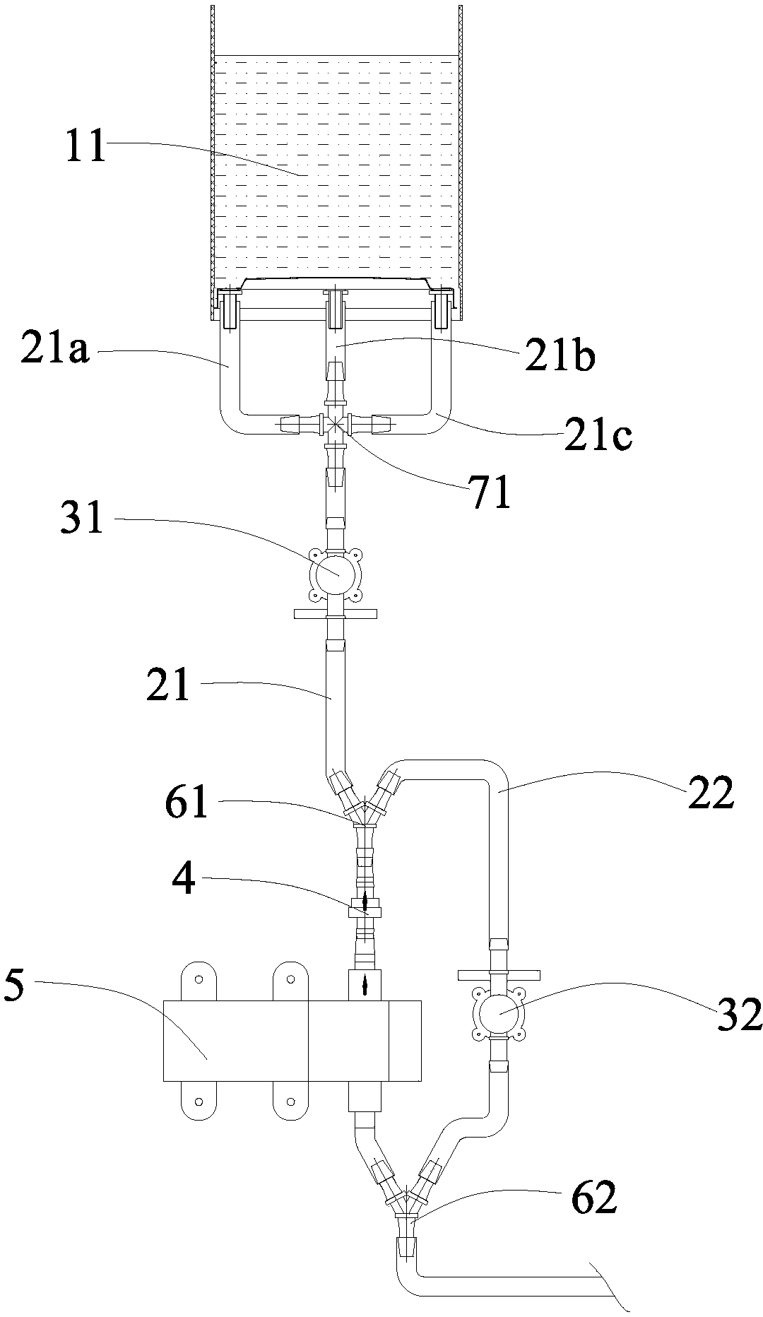
[0015] Such as figure 2 As shown, the automatic water inlet and drainage structure of the water bath includes a water bath tank body 11, a liquid level sensor is installed in the tank body 11, and three first pipeline branches 21a, 21b and 21c are connected to the bottom of the tank body 11, and the first pipeline branch Roads 21a, 21b and 21c communicate with the first pipeline 21 by four-way 71, and the first pipeline 21 is equipped with the first electromagnetic valve 31, check valve 4 and self-priming pump 5 successively from top to bottom, and the second pipeline 22 communicates with the first pipeline 21 through the tee 61 and the tee 62, the upper nozzle of the second pipeline 22 is located between the first electromagnetic valve 31 and the one-way valve 4, and the lower nozzle of the second pipeline 22 is located at The lower end of the self-priming pump 5, the second pipeline 22 is equipped with a second electromagnetic valve 32, and the liquid level sensor, the firs...
Embodiment 3
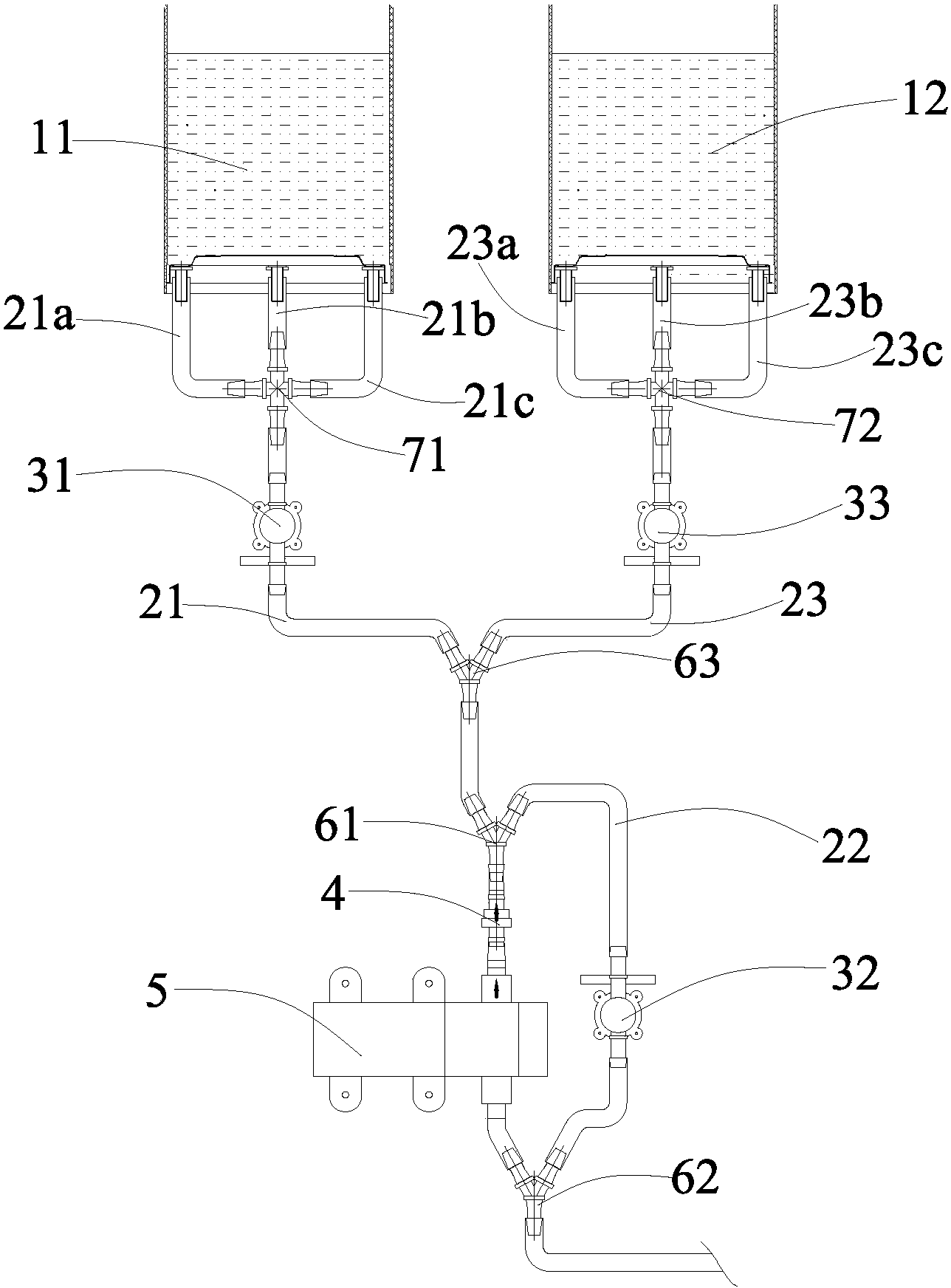
[0018] Such as image 3 As shown, the automatic water inlet and drainage structure of the water bath includes a first tank body 11 and a second tank body 12. There are liquid level sensors in the first tank body 11 and the second tank body 12, and three third tank bodies are connected to the bottom of the first tank body 11. One pipeline branch 21a, 21b and 21c, the bottom of the second tank body 12 is connected with three third pipeline branches 23a, 23b and 23c, the first pipeline branch 21a, 21b and 21c are connected with the first four-way 71 The pipeline 21 communicates, and the third pipeline branches 23a, 23b and 23c communicate with the third pipeline 23 by the four-way 72. The first solenoid valve 31 is installed on the first pipeline 21, and the third pipeline 23 is equipped with a third Electromagnetic valve 33, the third pipeline 23 communicates with the first pipeline 21 by the tee 63, the first pipeline 21 is connected with the second pipeline 22 below the tee 63...
PUM
 Abstract
Description
Claims
Application Information
 - R&D
- Intellectual Property
- Life Sciences
- Materials
- Tech Scout
- Unparalleled Data Quality
- Higher Quality Content
- 60% Fewer Hallucinations
Browse by: Latest US Patents, China's latest patents, Technical Efficacy Thesaurus, Application Domain, Technology Topic, Popular Technical Reports.
© 2025 PatSnap. All rights reserved.Legal|Privacy policy|Modern Slavery Act Transparency Statement|Sitemap|About US| Contact US: help@patsnap.com