Single-main-shaft box one-time clamping double-end phase friction welder

A friction welding machine and single-spindle technology, applied in auxiliary devices, welding equipment, welding equipment, etc., can solve problems such as unsatisfactory problems and inability to realize fixed-phase welding, so as to reduce investment, improve welding production efficiency, and avoid loss of precision Effect

Active Publication Date: 2014-01-22
哈尔滨正晨焊接切割设备制造有限公司
View PDF7 Cites 7 Cited by
  • Summary
  • Abstract
  • Description
  • Claims
  • Application Information

AI Technical Summary

Problems solved by technology

And it can only be used for the welding of three parts with symmetrical ends. There may be phase requirements between the parts at both ends, but fixed phase welding cannot be realized for the middle parts.
[0004] In order to overcome the above limitations, there are single-head phase friction welding machines and double-head phase friction welding machines driven by servo motors abroad, but there are still some problems that are not ideal.

Method used


Image

  • Single-main-shaft box one-time clamping double-end phase friction welder
  • Single-main-shaft box one-time clamping double-end phase friction welder

Examples


Embodiment 1

[0019] Embodiment 1: Two workpieces are welded at one time according to a fixed phase relationship.

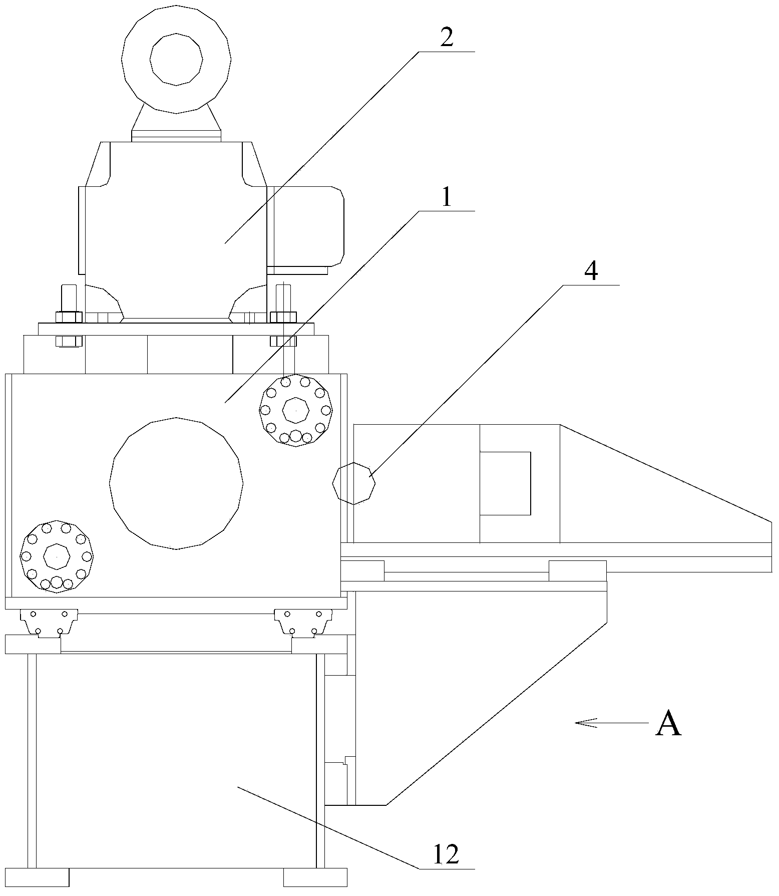
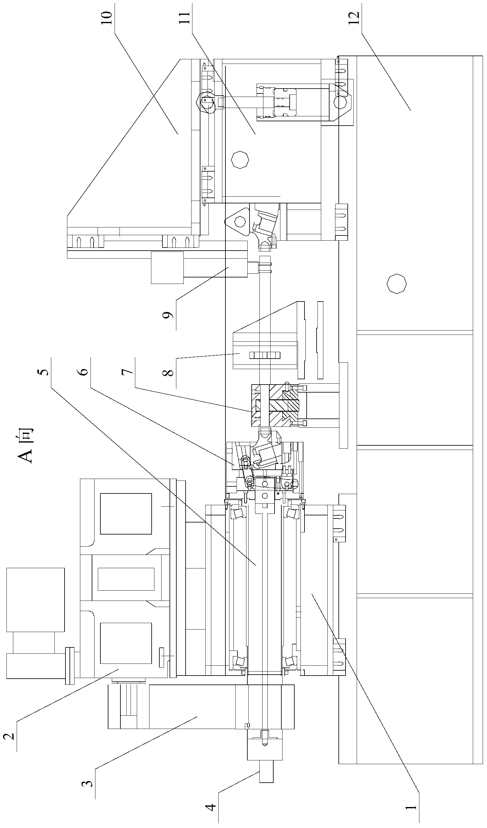
[0020] Before friction welding, the phase is set on the touch screen in the electronic control system, the spindle 5 and the rotary fixture 6 stop at the initial phase, and the two workpieces are respectively clamped in the rotary fixture 6 and the fixed fixture 7 according to the fixed initial phase relationship. Center frame 8 is used for auxiliary positioning, and roller center frame 9 is suspended in the air. After moving, the pushing device 10 directly pushes against the workpiece in the fixing fixture 7 .

[0021] Start the hydraulic station and the DC motor, the workpiece in the rotary fixture 6 rotates under the drive of the DC motor assembly 2 and the synchronous pulley transmission mechanism 3, the other workpiece is clamped by the fixed fixture 7, and the headstock 1 is driven by the hydraulic system Moving to the workpiece fixed in the fixture 7, the spindle box 1...

Embodiment 2

[0022] Embodiment 2: Three workpieces are welded twice according to a fixed phase relationship.

[0023] When two identical workpieces are required to be welded symmetrically at both ends of the third workpiece, the three workpieces are clamped at one time according to the fixed phase relationship, and the double-headed workpieces with fixed phase angle requirements can be welded twice with a single headstock drive.

[0024] Before friction welding, the phase is set on the touch screen in the electronic control system, the spindle 5 and the rotating fixture 6 stop at the initial phase, and the two workpieces are respectively clamped in the rotating fixture 6 and the fixed fixture 7 according to the fixed initial phase relationship. Center frame 8 is used for auxiliary positioning, and roller center frame 9 is suspended in the air. The workpiece three in the lifting device 10 is positioned and clamped by the workpiece positioning and clamping device 11 after moving, and direct...


PUM


Abstract

The invention provides a single-main-shaft box one-time clamping double-end phase friction welder and belongs to the technical field of friction welders. A main shaft box is arranged on the upper portion of one side of a lathe bed. A tool locating clamping device is arranged on the upper portion of the other side of the lathe bed. A back pushing device is arranged on the upper portion of the tool locating clamping device. A main shaft is arranged in the main shaft box. A coding machine is arranged at the outer end of the main shaft. A direct-current motor component is arranged on the upper portion of the main shaft box. The direct-current motor component and the main shaft are in transmission connection through a synchronous pulley transmission mechanism. A rotating clamp is arranged at the inner end of the main shaft. During using, three workpieces are clamped at one time, accuracy loss caused by clamping again in secondary welding in a 180-degree-turning mode is avoided, welding phase accuracy is improved, and meanwhile welding production efficiency is improved. A direct-current motor is used for accurately controlling the angular velocity and the angular displacement of the main shaft, and accurate phase control of welding friction is achieved. The phase control accuracy can reach +/-0.5 degree.

Description

technical field [0001] The invention relates to a double-head phase friction welding machine with a single spindle box once clamped, and belongs to the technical field of phase friction welding machines. Background technique [0002] If a pair of workpieces to be welded is a round tube or a round rod, it can stop at any circumferential position when braking after welding; if a pair of workpieces to be welded is a special-shaped or square tube, it must stop at a fixed angle when braking after welding On the other hand, the phase relationship determined by the two workpieces is maintained, which is phase friction welding. [0003] Sometimes a joint is welded at both ends of a workpiece, and there is a fixed angle requirement between the joints at both ends, that is, "double-head" phase friction welding. In order to ensure a fixed angle, the friction welding machine usually uses the conjugate drive rotation of the weldments at both ends, which is actually a mechanical synchron...

Claims


Application Information

Patent Timeline
Patent Type & Authority Applications(China)
IPC IPC(8): B23K20/12B23K20/26B23K37/04
CPCB23K20/122B23K20/126
Inventor 邱凯
Owner 哈尔滨正晨焊接切割设备制造有限公司
Why Eureka
Try Eureka