AI technical title is built by PatSnap AI team. It summarizes the technical point description of the patent document.
A technology for controlling torque gyroscopes and magnetic levitation, which is applied in the direction of space navigation vehicle guidance devices, transportation and packaging, and space navigation aircraft, etc. To achieve the effect of compact structure, reduced volume and weight, and light weight
Active Publication Date: 2019-08-06
BEIHANG UNIV
View PDF11 Cites 0 Cited by
Summary
Abstract
Description
Claims
Application Information
AI Technical Summary
This helps you quickly interpret patents by identifying the three key elements:
Problems solved by technology
Method used
Benefits of technology
Problems solved by technology
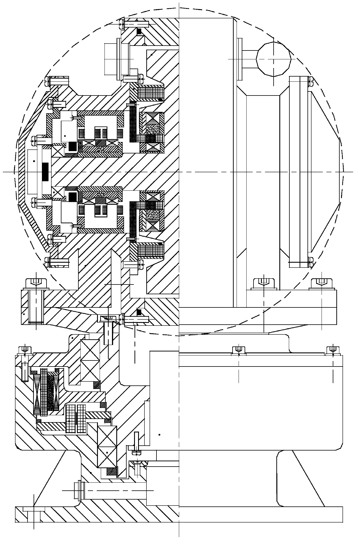
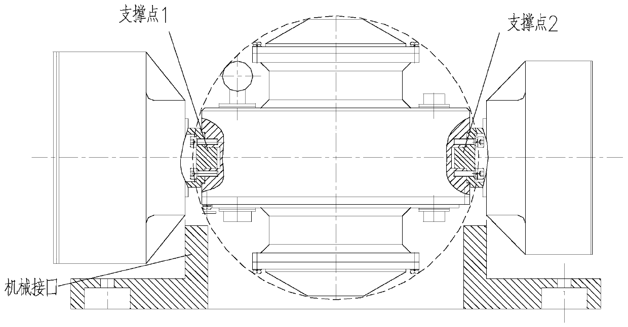
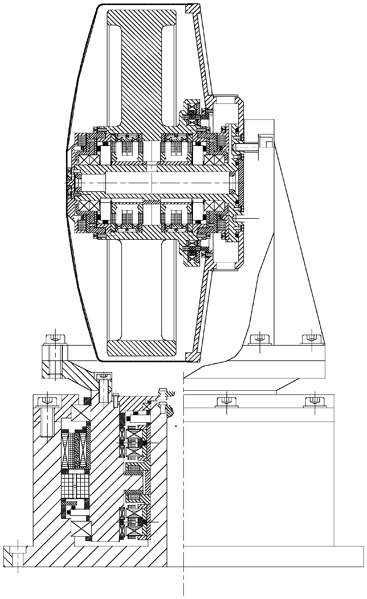
The existing single-frame control moment gyroscope and flywheel rotor system are all supported by mechanical bearings. Due to the wear of the mechanical bearings, there are still many restrictions on the speed and service life. The system brings a disturbance torque, which affects the stability of the spacecraft; Chinese invention patent ZL200710065550.1, as attached figure 1 The gyro rotor in the single-frame magnetic levitation control moment gyro shown in the figure adopts the inner rotor structure. Due to the rotor with the same mass and volume, the moment of inertia of the gyro rotor with the inner rotor structure is smaller than the angular momentum of the gyro rotor with the outer rotor structure. At the same angular velocity , the angular momentum of the gyro rotor with the inner rotor structure is smaller than that of the gyro rotor with the outer rotor structure, so when outputting the same angular momentum, the volume and mass of the control moment gyroscope with the inner rotor structure are relatively large; some single frame The magnetic levitation control moment gyro adopts the method of supporting at both ends. figure 2 , the frame system has two support points (support point 1, 2), and a pair of mechanical bearings are required at both ends. The frame system of the control moment gyroscope of this structure needs to provide a large turning space for the rotor system, so the frame system The volume and weight are relatively large, and the mechanical interface with the satellite is relatively large, so it is not suitable for the control torque gyro with small and medium torque output; Chinese invention patent ZL200710065551.6, as attached image 3 The flywheel and frame of the single-frame control torque gyroscope shown above use magnetic suspension bearings. The structure and control system of the control torque gyroscope with this structure are relatively complex, with relatively large volume and mass, and are not suitable for control torque gyroscopes with small and medium torque outputs.
[0003] Chinese patent application CN200710098750.7 provides a magnetic levitation reaction flywheel without a frame system, and the output torque is relatively small; Chinese patent application CN200610011561.7 provides a magnetic levitation turntable, which is not suitable as an actuator for spacecraft attitude control ; Chinese patent application CN200610011579.7, provides a kind of magnetic levitation energy storage flywheel, but this energy storage flywheel is used for the energy storage device of spacecraft, is not suitable as spacecraft attitude control actuator; Chinese patent application CN200710304236.4 , a dual-frame maglev control moment gyroscope is given. There are two frame systems, the structure is complex, and there is coupling between the inner frame system and the outer frame system, so the control is difficult
CN201510555829.2; patent application CN201510555829.2, which provides a high-torque magnetic levitation control sensitive gyroscope, but the frame system has two support points, and a pair of mechanical bearings are required at both ends. The frame system of the control moment gyroscope with this structure It is necessary to provide a large turning space for the rotor system, so the volume and weight of the frame system are relatively large, and the mechanical interface with the satellite is also relatively large, which is not suitable for the control torque gyroscope with small and medium torque output
Method used
Image
Click on the blue label to locate the original text in one second.
Reading with bidirectional positioning of images and text.
Examples
Embodiment Construction
[0023] The present invention will be further described below in conjunction with the accompanying drawings and specific embodiments.
[0024] Such as Figure 4 and Figure 5, the present invention is mainly composed of flywheel system and frame system, wherein the flywheel system is mainly composed of flyweight 2, radial magnetic suspension bearing 8, radial position sensor 6, axial passive magnetic suspension bearing 5, motor 4, protective bearing 1, The sealing shell 3 and the shaft seat 7 are composed, the protective bearing 1 is located in the middle of the flywheel, the two sides are the sealing shell 3 and the shaft seat 7, the upper and lower sides of the protective bearing 1 are the flyweight 2, the radial magnetic suspension bearing 8, The radial position sensor 6, the axial passive magnetic suspension bearing 5, and the motor 4, wherein the flyweight 2, the radial magnetic suspension bearing 8 rotor part, the axial passive magnetic suspension bearing 5 rotor part an...
PUM
Abstract
The invention discloses a magnetic suspension control moment gyro device. The magnetic suspension control moment gyro device is formed by a flywheel system and a frame system. The flywheel system is formed by fly hammers, radial magnetic suspension bearings, radial position sensors, axial driven magnetic suspension bearings, motors, a protective bearing, a sealing shell, an axle seat and the like. The protective bearing is located in the middle of a flywheel, the sealing shell and the axel seat are located on the two sides of the flywheel, and the fly hammers, the radial magnetic suspension bearings, the radial position sensors, the axial driven magnetic suspension bearings and the motors are sequentially arranged on the upper side and the lower side of the protective bearing from inside to outside. The frame system is formed by a support, a rotary disc, a torque motor, a bearing, a sleeve, a lock nut, a conductive slip ring, a photoelectric encoder, an end cap and a base. In the frame system, the support is connected with the axel seat and the rotary disc, the conductive slip ring is located in the middle of the rotary disc, and the sleeve, the bearing, the locking nut, the photoelectric encoder and the end cap are outwards located on the rotary disc. According to the magnetic suspension control moment gyro device, the axial driven magnetic suspension bearings and the photoelectric encoder are adopted, the size, the weight and vibration are reduced, control precision is improved, and the response speed is increased.
Description
technical field [0001] The invention relates to the technical field of control moment gyro, in particular to a magnetic levitation control moment gyro device, which can be used for large-angle attitude maneuver control and attitude stability control of spacecraft such as agile maneuvering satellites and large satellites. Background technique [0002] Modern space vehicles such as agile mobile satellites used in urban surveying and mapping, precision agriculture, and disaster monitoring, or satellite platforms for large-scale satellites for earth observation or scientific research, have higher and higher requirements for stability and flexibility in large-angle maneuvers. Satellites that can maneuver at large angles can improve the efficiency and quality of Earth observation. The single-frame control moment gyro is one of the main actuators used for attitude control of spacecraft. The existing single-frame control moment gyroscope and flywheel rotor system are all supported ...
Claims
Application Information
Patent Timeline
Application Date:The date an application was filed.
Publication Date:The date a patent or application was officially published.
First Publication Date:The earliest publication date of a patent with the same application number.
Issue Date:Publication date of the patent grant document.
PCT Entry Date:The Entry date of PCT National Phase.
Estimated Expiry Date:The statutory expiry date of a patent right according to the Patent Law, and it is the longest term of protection that the patent right can achieve without the termination of the patent right due to other reasons(Term extension factor has been taken into account ).
Invalid Date:Actual expiry date is based on effective date or publication date of legal transaction data of invalid patent.

