
Improved structure of clamping jaw for printed circuit board drill bit ring assembling machine

A technology of printed circuit board and improved structure, which is applied in chucks, manipulators, metal processing, etc., and can solve the problems of chuck wear, short distance, and drop of jaws

Inactive Publication Date: 2014-01-22
竞陆电子(昆山)有限公司
View PDF8 Cites 3 Cited by
  • Summary
  • Abstract
  • Description
  • Claims
  • Application Information

AI Technical Summary

Problems solved by technology

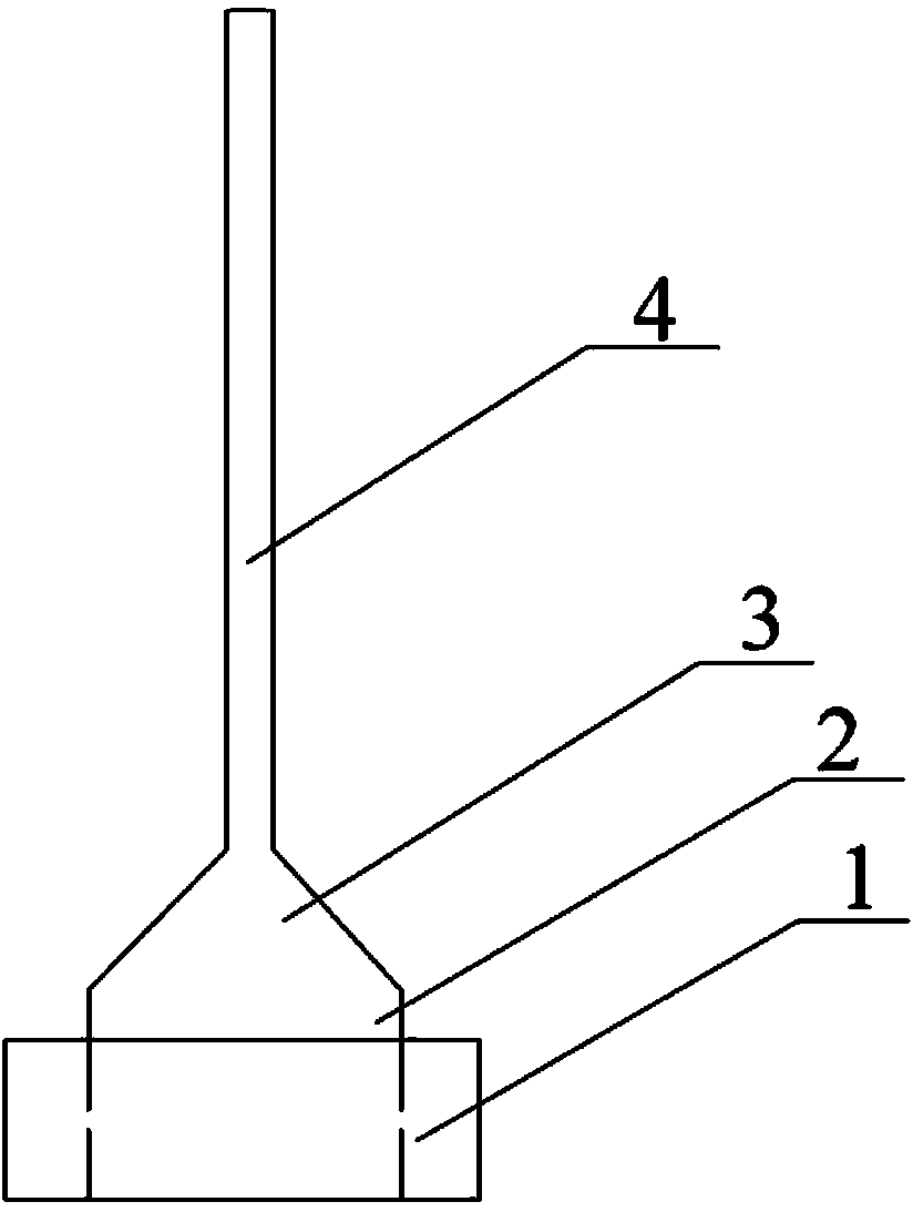
However, because the drill body 4 of the drill with a small diameter (such as a drill with a diameter of 1.25-1.50 mm) is too long for printed circuit boards, the distance between the taper 3 of the drill shank and the shank 2 of the collar 1 is relatively short. (like figure 1 As shown), the chuck part of the jaw cannot grasp the drill pin, so that the upper ring machine often stops or the drill bit falls during operation
In addition, the clamping jaws of the clamping drill shank clamp the drill shank each time, and the drill shank is made of metal, which will cause serious wear and tear on the chuck of the clamping jaw, and it will easily lead to unstable clamping, thus shortening the clamping jaws service life

Method used


Image

  • Improved structure of clamping jaw for printed circuit board drill bit ring assembling machine
  • Improved structure of clamping jaw for printed circuit board drill bit ring assembling machine
  • Improved structure of clamping jaw for printed circuit board drill bit ring assembling machine

Examples


Embodiment Construction

[0023] combine Figure 1 to Figure 3 The present invention is described in further detail.

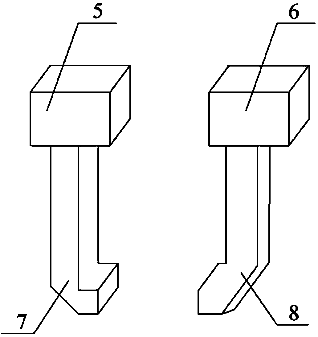
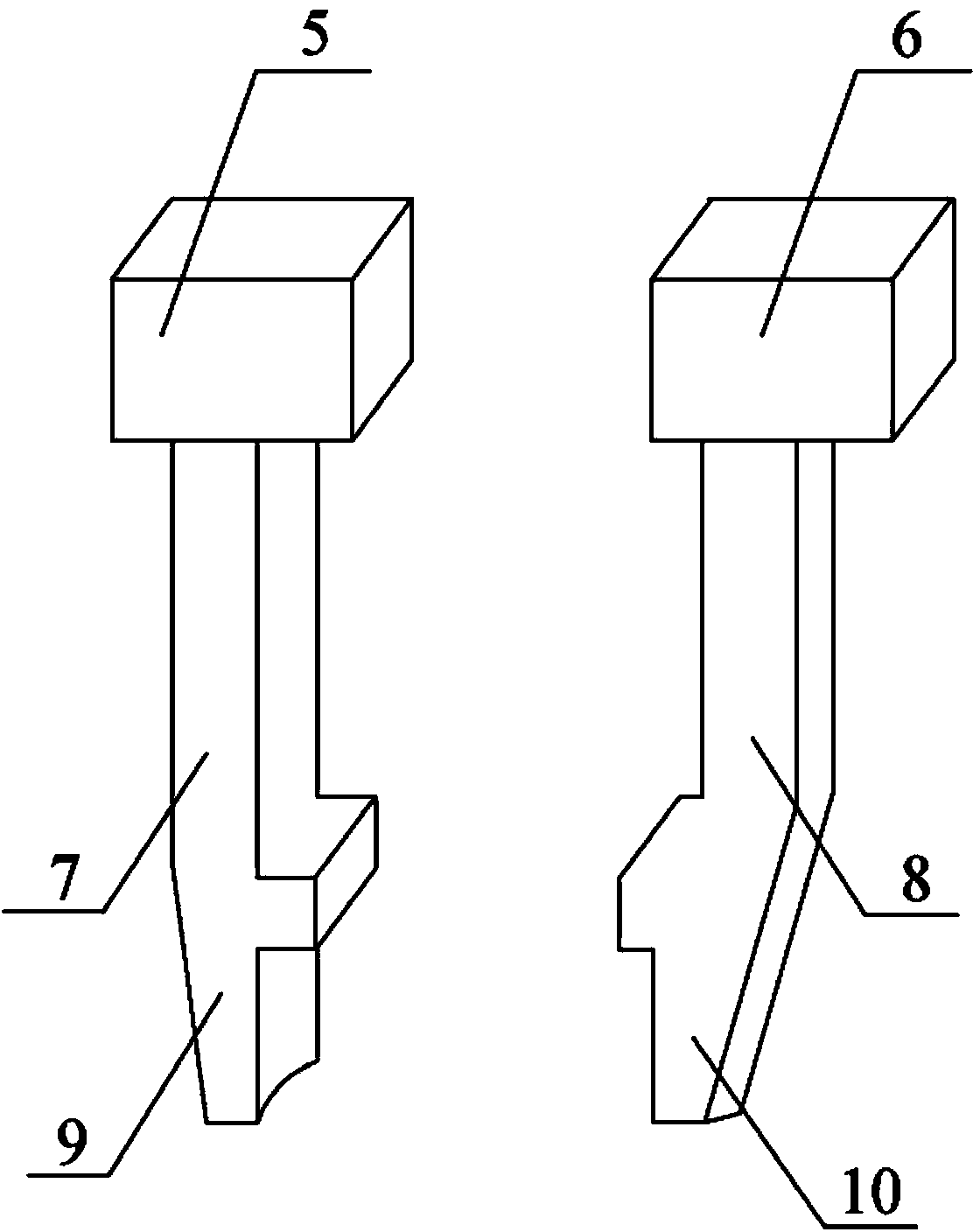
[0024] An improved structure of the clamping jaws for the upper ring machine of printed circuit board drills, including a first clamping jaw 5 and a second clamping jaw 6 capable of relative clamping, and a first clamping head 7 is provided at the end of the first clamping jaw , the end of the second jaw is provided with a second chuck 8, the first and second chucks are opposing clamping blocks, and the end of the first chuck 7 extends downward to form a first clamping end 9 , the end of the second chuck 8 extends downwards to form a second clamping end 10 , and the opposite surfaces of the first and second clamping ends are shaped to match the outer peripheral surface of the collar 1 . Wherein the first clamping head 7 is a clamping block with an "L"-shaped structure, and the second clamping head 8 is a clamping block that is mirror image symmetrical to the first clamping head. The ...


PUM

PropertyMeasurementUnit
Lengthaaaaaaaaaa
Lengthaaaaaaaaaa

Abstract

The invention discloses an improved structure of a clamping jaw for a printed circuit board drill bit ring assembling machine. The improved structure is characterized in that the end portions of a clamping head of a drilling bit handle clamping type clamping jaw for an existing ring assembling machine extend downwards to form the clamping ends, and the opposite faces of the pair of clamping ends are in a shape matched with the peripheral face of a lantern ring so that the lantern ring on a drill bit can be directly clamped rather than the traditional mode that the drill bit drill handle portion is clamped. The improved clamping jaw is free of influences of the diameter of the drill bit and the length of a knife, the problem that the drill bit can not be clamped by the clamping head is solved, and due to the fact that the lantern ring is made of plastic materials, the situation that the clamping jaw is seriously abraded is avoided.

Description

technical field [0001] The invention relates to a component part for a ring-clamping machine for a drill bit of a printed circuit board, in particular to an improved structure of a clamping jaw for a ring-clamping machine for a drill bit of a printed circuit board. Background technique [0002] In the drilling process of printed circuit board (PCB), in order to avoid damage to the printed circuit and electronic components on the circuit board when drilling, and to ensure that the drilling depth meets the required requirements, special The shank of the drill bit is sleeved with a protective collar (such as figure 1 As shown), the commonly used PCB drill rings on the market are all made of plastic materials, and the outer diameter of the rings is a uniform value, and the common one is generally 7.6mm. The process of setting the collar is usually completed by the upper ring machine, but because the distance from the bottom of the collar to the drill tip of drills with differen...

Claims


Application Information

Patent Timeline
IPC IPC(8): B23P19/00B25J15/08
CPCB23P19/001B25J15/08
Inventor 李泽清
Owner 竞陆电子(昆山)有限公司
Learn More