Deep hole inner wall strain gauge adhering tool for steel rolling sensor

A strain gauge and sensor technology, which is applied in the field of strain gauge patch tooling on the inner wall of deep holes, can solve the problems of difficulty in separating the strain gauge from the tooling, easy detachment from the strain gauge, and inaccurate patch positions, etc., achieving strong versatility and ease of use The effect of wide range and convenient pressure

Active Publication Date: 2014-01-22
YUYAO TONGYONG METER
View PDF7 Cites 21 Cited by
  • Summary
  • Abstract
  • Description
  • Claims
  • Application Information

AI Technical Summary

Problems solved by technology

[0004] The present invention overcomes that the strain gauge patching device in the prior art is difficult to be used for patching the inner wall of a deep hole with a small diameter. Insufficient separation provides a deep hole inner wall strain gauge patch for rolling steel sensors that can

Method used


Image

  • Deep hole inner wall strain gauge adhering tool for steel rolling sensor
  • Deep hole inner wall strain gauge adhering tool for steel rolling sensor
  • Deep hole inner wall strain gauge adhering tool for steel rolling sensor

Examples


Embodiment 1

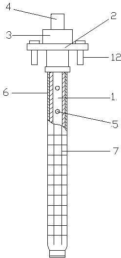
[0027] Embodiment 1: as figure 1 and figure 2 The shown one is a deep hole inner wall strain gauge patch tooling for rolling steel sensors, including a tube body 1 with one end closed, and a positioning seat 2 connected to the opening end of the tube body. The tube body 1 is a stainless steel tube, and the tube body 1 is connected to the positioning The seat 2 is threadedly connected, and a positioning hole is provided around the positioning seat 2, and a positioning pin 12 is arranged in the positioning hole; a ball valve 3 is provided on the positioning seat, and an air joint 4 is provided at the outer end of the positioning seat, and one end of the ball valve 3 is connected to the The inside of the pipe body is connected, and the other end of the ball valve 3 is connected with the gas joint 4. The side wall of the pipe body is provided with a number of vent holes 5, and the outer side of the pipe body is provided with a silicone sleeve 6. The two ends of the silicone sleev...

Embodiment 2

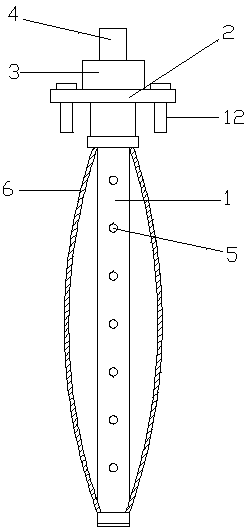
[0028] Embodiment 2: as image 3 The shown one is a deep hole inner wall strain gauge patch tooling for rolling steel sensors, including a tube body 1 with one end closed, and a positioning seat 2 connected to the opening end of the tube body. The tube body 1 is a stainless steel tube, and the tube body 1 is connected to the positioning The seat 2 is threadedly connected, and a positioning hole is provided around the positioning seat 2, and a positioning pin 12 is arranged in the positioning hole; a ball valve 3 is provided on the positioning seat, and an air joint 4 is provided at the outer end of the positioning seat, and one end of the ball valve 3 is connected to the The inside of the pipe body is connected, and the other end of the ball valve 3 is connected with the gas joint 4. The side wall of the pipe body is provided with a number of vent holes 5, and the outer side of the pipe body is provided with a silicone sleeve 6. The two ends of the silicone sleeve 6 It is seal...


PUM


Abstract

The invention discloses a deep hole inner wall strain gauge adhering tool for a steel rolling sensor. The deep hole inner wall strain gauge adhering tool for the steel rolling sensor comprises a pipe body and a locating base. The locating base is provided with a ball valve, and a gas connector is arranged at the outer end of the locating base. A plurality of exhaust holes are formed in the side wall of the pipe body, the outer side of the pipe body is sleeved with a silicon rubber sleeve, and the two ends of the silicon rubber sleeve are connected with the outer sides of the two ends of the pipe body in a sealing mode. A silicon rubber inner sleeve is arranged between the inner side of the silicon rubber sleeve and the outer side of the pipe body. A plurality of annular grooves are formed in the outer side surface of the pipe body at intervals in the axial direction, and a plurality of hoop rings are arranged on the outer side surface of the silicon rubber inner sleeve. Accordingly, the deep hole inner wall strain gauge adhering tool for the steel rolling sensor has the advantages that a strain gauge can adhere to the deep hole inner wall accurately, the adhering position is accurate, the strain gauge can be separated from the tool conveniently after adhesion, the pressure on the strain gauge acts on the strain gauge stably and continuously in the adhering process and can be adjusted conveniently, and the strain gauge can adhere to the deep hole inner wall firmly.

Description

technical field [0001] The invention relates to the technical field of sensor processing, in particular to a deep hole inner wall strain gauge pasting tooling for a steel rolling sensor. Background technique [0002] At present, for the rolling steel sensor used in the metallurgical industry, the strain gauge is pasted on the inner wall of the deep hole. Due to the small diameter of the deep hole, it cannot be directly pasted manually, and the strain gauge needs to be pasted with the help of tooling. Some of the common patch tooling nowadays cannot achieve high-quality patching on the inner wall of the deep hole. Usually, the position of the strain gauge sticking is relatively large, or the strain gauge is not firmly pasted, and it is easy to fall off, which seriously affects the performance of the sensor. [0003] For example: Chinese Patent Authorization Announcement No.: CN2326948Y, the authorized announcement date was June 30, 1999, which discloses an in-pipe patch tool,...

Claims


Application Information

Patent Timeline
IPC IPC(8): F16B11/00
Inventor 翁建明褚冬军眭博罗伏隆
Owner YUYAO TONGYONG METER
Why Eureka
Try Eureka