Computer senaille embroidery die head

A technology of drill piece embroidery and machine head, which is applied to the mechanism of embroidery machine, embroidery machine, automatically controlled embroidery machine, etc. reliability and reliability, improve work efficiency, and improve quality

Inactive Publication Date: 2011-08-17
陈格
View PDF5 Cites 0 Cited by
  • Summary
  • Abstract
  • Description
  • Claims
  • Application Information

AI Technical Summary

Problems solved by technology

The above-mentioned patent adopts the turntable structure of multi-suction rods, which can realize the suction of the drill piece and the sticking of the drill piece at the same time after ventilation, which improves the work efficiency. However, the machine head in the above-mentioned patent drives the claw plate through its own suction shaft. Rotation, usually an embroidery machine is equipped with multiple machine heads side by side. In order to ensure the synchronization of the work of each machine head, the suction shaft of each machine head is covered with a shaft sleeve, and a timing belt pulley is also sleeved outside the shaft sleeve. In order to ensure the working synchronization of different machine head patches, this structure takes up a lot of space, the connection is more complicated, and the synchronization is poor, it is difficult to guarantee the quality of the patch; in addition, the suction rod on each claw plate in the above patent They are all fixed on the claw plate. Due to the small particle size of the drill chip, it is easy to block the suction nozzle. On the suction shaft, in this way, it is necessary to remove the claw disc from the suction shaft before the suction rod can be removed. The operation is time-consuming and laborious, and it is very inconvenient. The assembly accuracy of the machine head changes, such as the reduction of synchronization, which in turn affects the patch effect of drill embroidery

Method used


Image

  • Computer senaille embroidery die head
  • Computer senaille embroidery die head
  • Computer senaille embroidery die head

Examples


Embodiment Construction

[0030]The present invention will be further described in detail below with reference to the embodiments of the accompanying drawings.

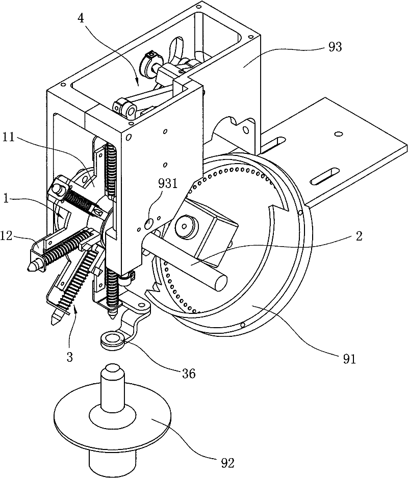
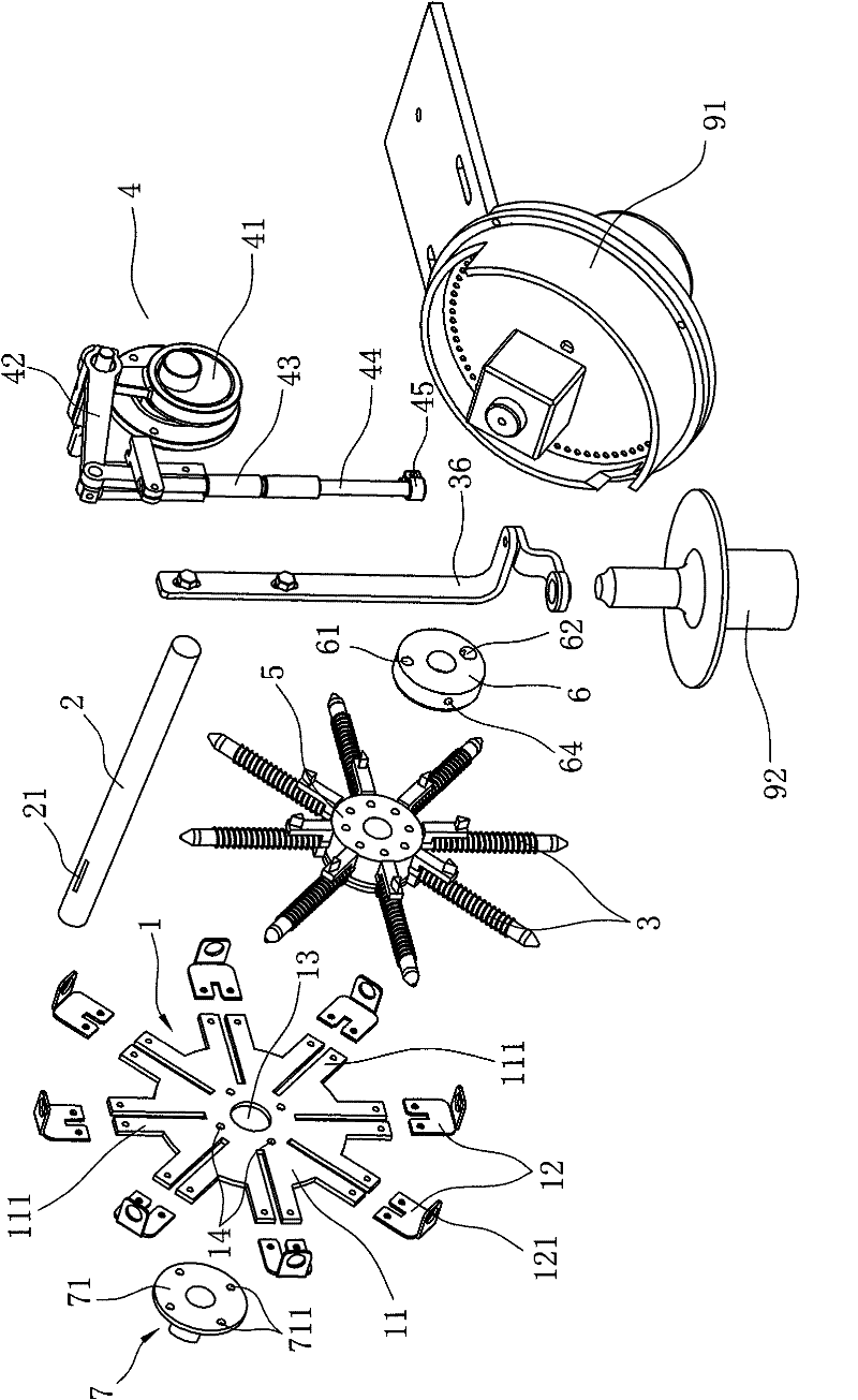
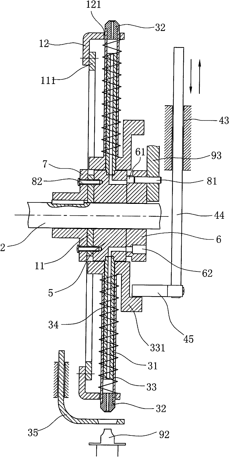
[0031] like Figure 1 to Figure 5 As shown, it is a schematic diagram of the structure of the drill head embroidery head of the present invention, and the head includes a suction claw mechanism, a pressing rod mechanism and an air supply device;

[0032] Among them, the suction claw mechanism has a rotatable claw plate 1, the claw plate 1 has a central hole 13 and is directly penetrated on the M-axis 2, and the claw plate 1 includes a main body 11 and a bracket 12 detachably connected to the main body. 11 has a circular fixed plate in the center and claw feet 111 radially arranged in a spoke shape along the circumference of the fixed plate. At the end of each claw foot 111, in order to facilitate the replacement and disassembly of the suction rod, the bracket 12 is L-shaped. Small hole 121, the vertical edge of the L-shaped bracket 12 is fix...


PUM


Abstract

The invention discloses a computer senaille embroidery die head comprising a suction claw mechanism and a pressure lever mechanism, wherein, the suction claw mechanism comprises a rotary claw disk and a suction rod assembly. The invention is characterized in that the claw disk is arranged on an M shaft, the M shaft is also provided with an air supplying device comprising an air wheel hub and an air suction disk; the air wheel hub is fixed with the claw disk, first blind holes are distributed on the inner end surface of the air wheel hub, and the number of the first blind holes corresponds to the number of the suction rod assembly; the outer circumference of the air wheel hub is provided with round holes which are communicated with the first blind holes and correspond to the corresponding suction rod air paths; the outer end surface of the air suction disk is fixed with the frame, the air suction disk is provided with air suction holes which run through axially, and the air suction holes form one air conduction groove on the inner end surface of the air suction disk; the air conduction groove is provided with a groove mouth which ensures that suction sheet station is positioned on the position where two blind holes on the suction sheet station and on the paster station are simultaneously communicated with the air suction holes. Compared with the prior art, the invention is directly provided with the claw disk on the M shaft, which ensures the working synchronism of each die head, ensures precision of senaille embroidery and improves the quality of senaille embroidery products.

Description

technical field [0001] The invention relates to a machine head structure of an embroidery machine, in particular to a machine head structure of computerized drill piece embroidery. Background technique [0002] The head of the traditional computerized drill piece embroidery adopts a single-cylinder suction rod structure. The cylinder swings from the suction cup holding the drill piece to the position where the cloth is placed, which is just one working point. The specific working process is: the cylinder is first positioned The suction piece station (that is, the position of the suction piece plate) will suck up the drill piece, and then swing to the patch station (that is, above the fabric), and attach the drill piece particles sucked from the suction cup to the fabric. The working method of the above-mentioned machine head can only use the expansion and contraction and back and forth swing of a cylinder to alternately drive the suction rod to suck or stick the drill piece,...

Claims


Application Information

Patent Timeline
Patent Type & Authority Patents(China)
IPC IPC(8): D05C13/00D05C7/00
Inventor 陈格
Owner 陈格
Why Eureka
Try Eureka