A Method for Rapid Transition of Finite Element 3D Model Mesh

A three-dimensional model and finite element technology, applied in special data processing applications, instruments, electrical digital data processing, etc., can solve problems such as complex operation, small transition ratio, and difficulty in realizing finite element simulation of large components, achieving remarkable efficiency, The effect of saving the total number of grids, division efficiency and transition ratio improvement

Active Publication Date: 2017-01-11
HEILONGJIANG INST OF TECH
View PDF2 Cites 0 Cited by
  • Summary
  • Abstract
  • Description
  • Claims
  • Application Information

AI Technical Summary

Problems solved by technology

[0008] The purpose of the present invention is to solve the current grid transition method is limited to a single-direction transition method, that is, in a single direction, the transition ratio of the grid size ratio of the far end to the proximal end is 2 or 3 to perform multiple grid transitions. The transition method of the direction is not only small in transition ratio, but also complicated in operation, and it is difficult to realize the problem of finite element simulation of large components, and a fast transition method of finite element 3D model mesh is provided

Method used


Image

  • A Method for Rapid Transition of Finite Element 3D Model Mesh
  • A Method for Rapid Transition of Finite Element 3D Model Mesh
  • A Method for Rapid Transition of Finite Element 3D Model Mesh

Examples


specific Embodiment approach 1

[0031] Specific implementation mode one: combine Figure 1 to Figure 5 Describe this implementation mode, this implementation mode is realized through the following steps:

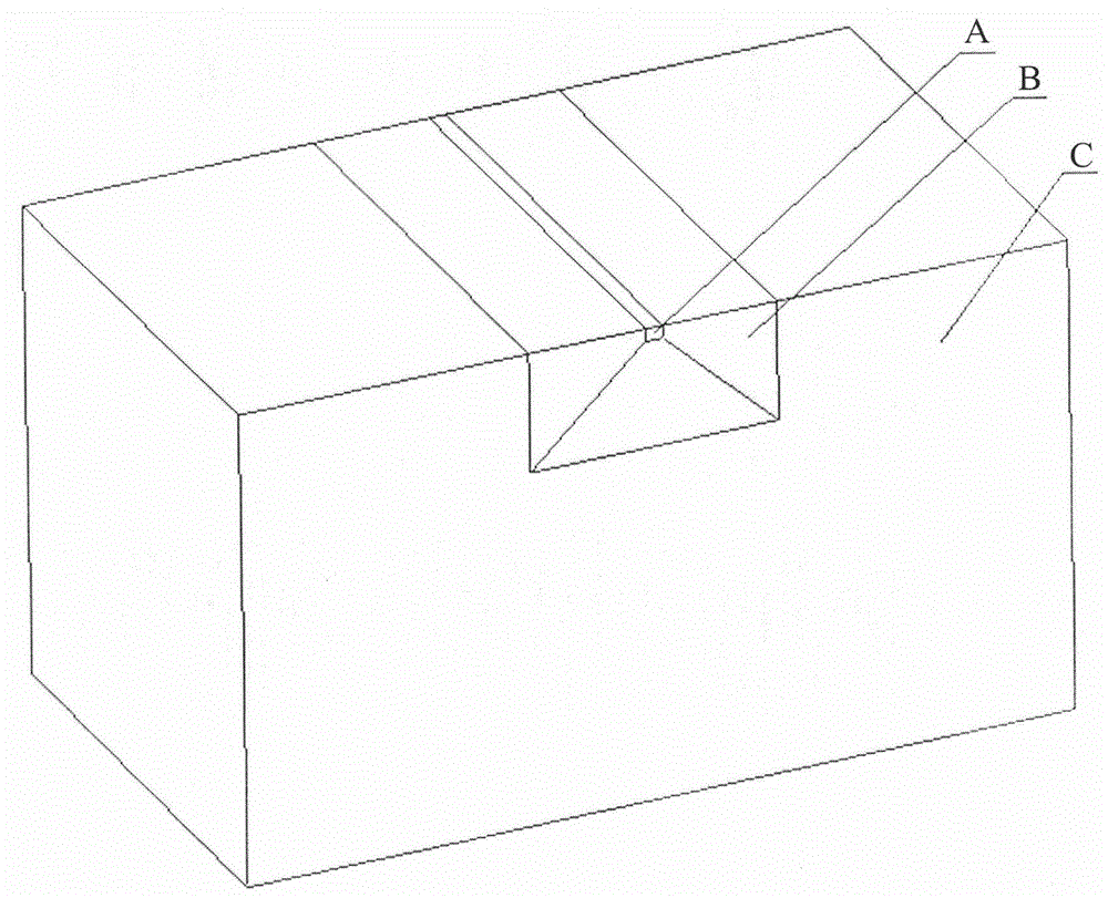
[0032] Step 1. First, divide the three-dimensional model of large and complex components into different regions:

[0033] According to the size of the calculated data change gradient of different parts of the component, it is divided into key area A, transition area B and non-key area C;

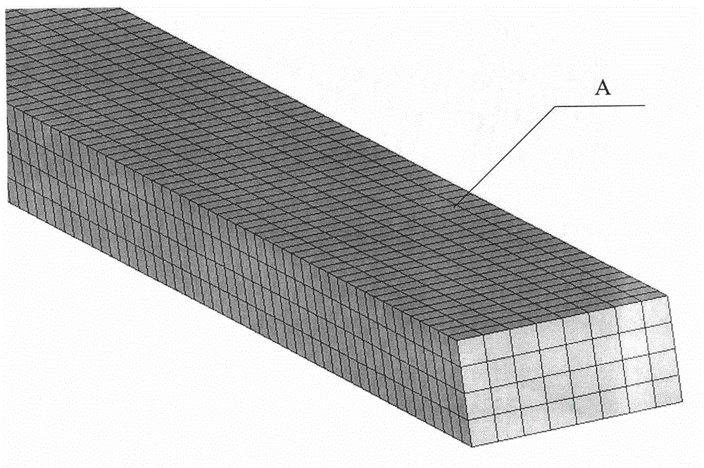
[0034] Step 2: Carry out grid division for key area A:

[0035] Divide several cubic or cuboid grids in the key area A, and the grids in the key area A should be dense; the key area A is the calculation data change gradient or key areas (such as stress concentration parts), in order to better reflect the data Change law, the finite element calculation has higher requirements on the grid quality of this area, and a relatively dense grid is used, so it is necessary to focus on dividing the key area A separately;

[0036...

specific Embodiment approach 2

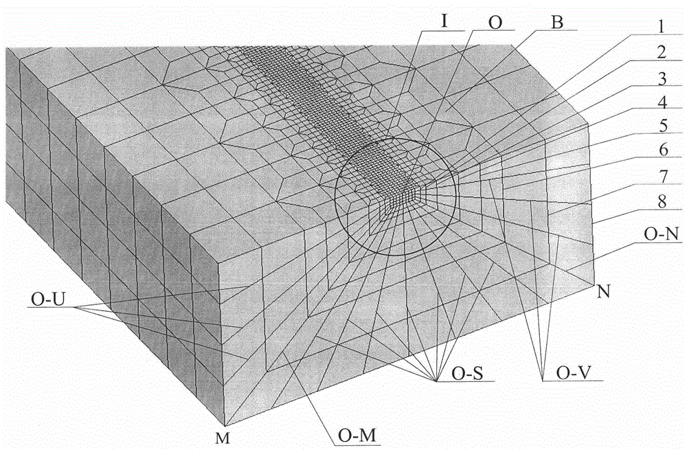
[0044] Specific implementation mode two: combination image 3 Describe this embodiment. In this embodiment, in step 3, the acute angle between the left bisecting slope O-M and the concave lower end surface is 45°, and the acute angle between the right bisecting slope O-N and the concave lower end surface is 45°. Other steps are the same as in the first embodiment.

specific Embodiment approach 3

[0045] Specific implementation mode three: combination Figure 4 Describe this embodiment. In this embodiment, in step 3, the grid size inside the transition area B matches the square grid size of the key area A. Other steps are the same as those in Embodiment 1 or 2.


PUM


Abstract

The invention discloses a method for quick transition of finite element three-dimensional model grids, relates to a method for finite element model grid transition and aims at solving the problem that an existing grid transition method is only limited to a single-direction transition means, namely, in the single direction, the grid size proportion of a far end and a short end is 2 or 3 and is used as the transition proportion to conduct multiple times of grid transition, and the means can not realize the finite element simulation of large components. The method comprises the steps of dividing a component into an important area, a transition area and a non-important area according to the size of calculation data change gradient of different parts of the component; dividing the important area into a plurality of grids in a shape of a cube or a cuboid, wherein grids in the important area A should be dense; conducting transition grid division on the transition area; dividing the non-important area into a plurality of grids in a shape of a cube or a cuboid, wherein grids in the non-important area should be sparse. Consequently, the grid division of the whole component is finished. The method is used for grid division of finite element model simulation modeling of a large or super large component.

Description

[0001] Technical field: [0002] The invention relates to a method for mesh transition of a finite element model, in particular to a method for realizing fast transition of a finite element three-dimensional model mesh. [0003] Background technique: [0004] The finite element method is a modern numerical calculation method developed rapidly with the development of electronic computers to solve mathematical and physical problems. It can analyze and solve static or dynamic mechanical properties, heat conduction, electromagnetic fields, fluid mechanics, etc. Linear or nonlinear question. The finite element method replaces the complex problem with a simpler problem and then solves it. The solution domain is regarded as composed of many small interconnected sub-domains called finite elements, and small units are analyzed. Generally, finite element analysis software is used to calculate actual engineering problems, and it is widely used in various fields such as machinery manufact...

Claims


Application Information

Patent Timeline
Patent Type & Authority Patents(China)
IPC IPC(8): G06F17/50
Inventor 王佳杰王国星许建平张颖王伟牛超楠单晓晨吴强
Owner HEILONGJIANG INST OF TECH
Why Eureka
Try Eureka