Temporary supporting rod for high-voltage line
A technology for temporary support and high-voltage wires, which is applied in the direction of overhead lines/cable equipment, etc., and can solve problems such as wire tension and power supply safety hazards
- Summary
- Abstract
- Description
- Claims
- Application Information
AI Technical Summary
Problems solved by technology
Method used
Image
Examples
Embodiment 1
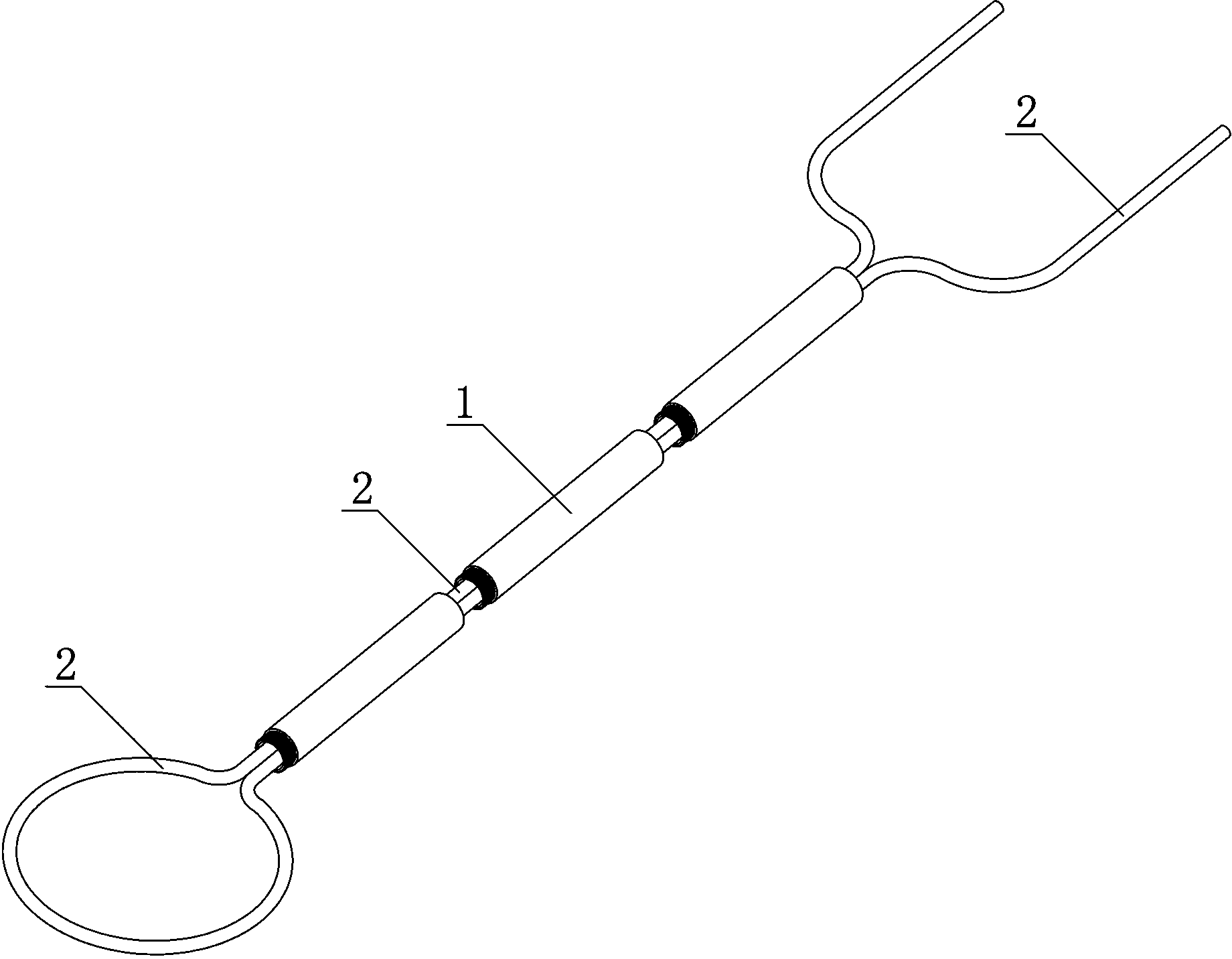
[0021] Such as figure 1 As shown, a temporary support rod for high-voltage electric wires includes an insulating support tube 1 and a fastening rope 2 , and the fastening rope 2 is folded in half and passed through the insulating support tube 1 . When in use, pass the fastening rope 2 around the high-voltage electric wire and pull up the high-voltage electric wire, then insert both ends of the fastening rope 2 into one end of the insulating support tube 1 at the same time, and pull it up from the insulating support tube 1. The other end stretches out, and then the two free ends of described fastening rope 2 are walked around tree branch and tied up, and described high-voltage electric wire is hoisted. If only the high-voltage wire is pulled up with the fastening rope 2, it will still shake a lot when the wind blows, so the function of the insulating support tube 1 is to control the distance between the high-voltage wire and the tree branches, so as to Reduce the swaying range...
Embodiment 2
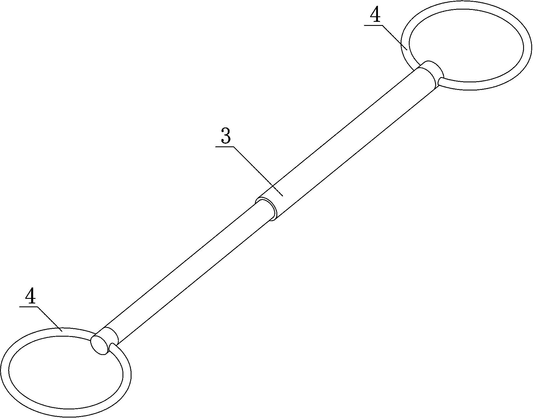
[0024] Such as figure 2 As shown, the difference between Embodiment 2 and Embodiment 1 is: a temporary support rod for high-voltage electric wires, including an insulating support rod 3 and an insulating fixing ring 4 that is rotatably connected to both ends of the insulating supporting rod 3, and the insulating fixing ring 4 The ring 4 is provided with movable openings. When in use, pass the drooping high-voltage wire through the movable opening into one of the insulating fixing rings 4, then pull up the high-voltage wire and hang the other insulating fixing ring 4 on the tree branch through the movable opening superior.
[0025] The movable opening can be a commonly used structure such as an elastic buckle. The purpose of rotating the insulating fixing ring 4 and the insulating support rod 3 is to adapt to the extending direction of the high-voltage electric wire and the extending direction of the branches of trees.
[0026] The insulating support rod 3 is a telescopic r...
Embodiment 3
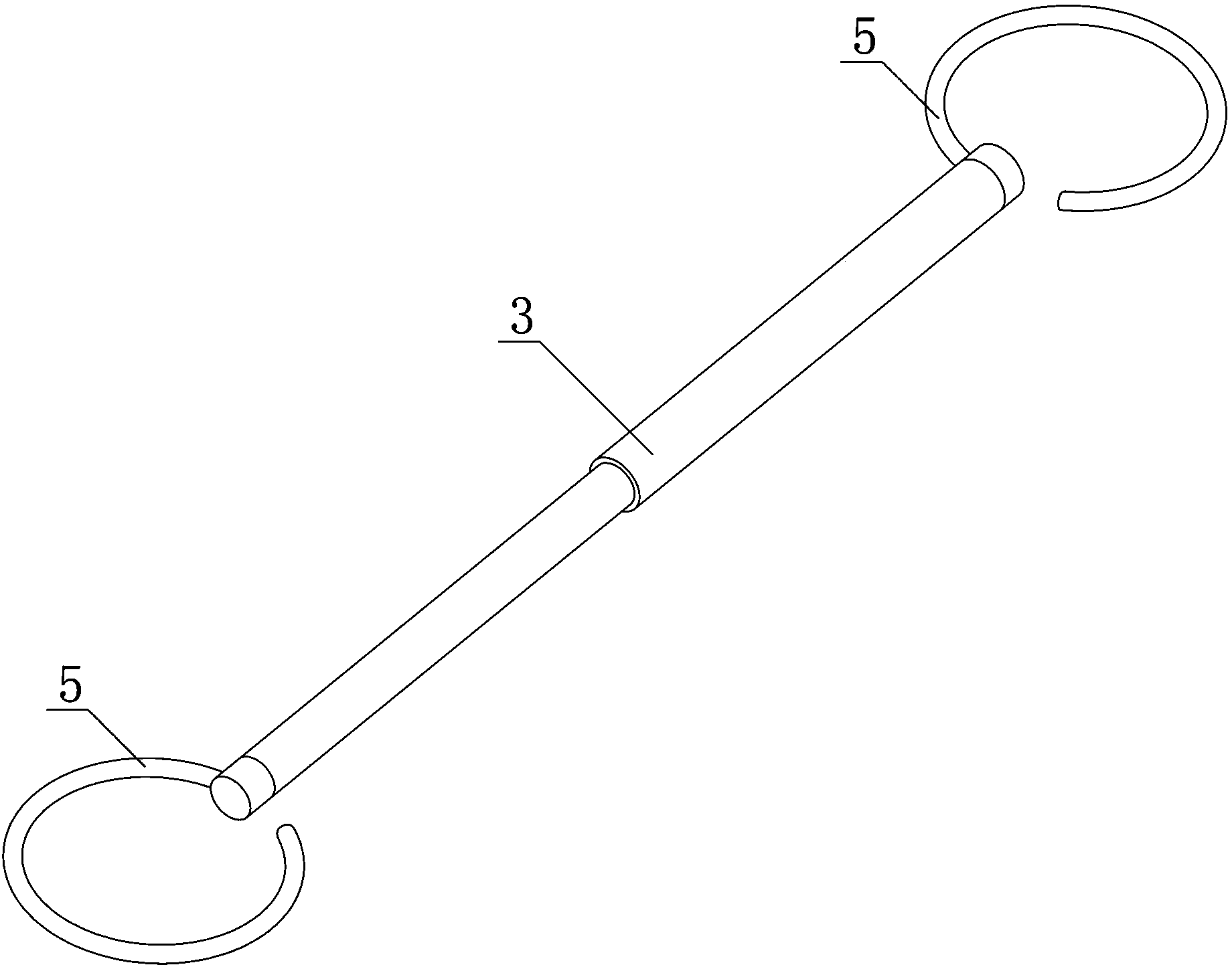
[0028] Such as image 3 As shown, the difference between embodiment 3 and embodiment 2 is: a temporary support rod for high-voltage electric wires, including an insulating support rod 3 and insulating hooks 5 respectively connected to both ends of the insulating support rod 3 in rotation. In this way, the insulating hook 5 is designed to replace the insulating fixing ring 4, so that the working process of hoisting high-voltage electric wires is more concise, and it can be hung up once.
PUM
 Abstract
Description
Claims
Application Information
 - R&D Engineer
- R&D Manager
- IP Professional
- Industry Leading Data Capabilities
- Powerful AI technology
- Patent DNA Extraction
Browse by: Latest US Patents, China's latest patents, Technical Efficacy Thesaurus, Application Domain, Technology Topic, Popular Technical Reports.
© 2024 PatSnap. All rights reserved.Legal|Privacy policy|Modern Slavery Act Transparency Statement|Sitemap|About US| Contact US: help@patsnap.com


