Charging device and method for inductive charging of electrical energy stores

A charging device and electric energy storage technology, applied in the direction of electric vehicle charging technology, charging stations, vehicle energy storage, etc., can solve the problem of anti-pollution vulnerability and other problems, and achieve no damage to accuracy, high position resolution, cost-saving effect

Active Publication Date: 2017-08-11
SIEMENS AG
View PDF10 Cites 0 Cited by
  • Summary
  • Abstract
  • Description
  • Claims
  • Application Information

AI Technical Summary

Problems solved by technology

[0004] Methods for ultrasonic positioning are also known, but these are also problematic due to their vulnerability to contamination

Method used


Image

  • Charging device and method for inductive charging of electrical energy stores
  • Charging device and method for inductive charging of electrical energy stores
  • Charging device and method for inductive charging of electrical energy stores

Examples


Embodiment Construction

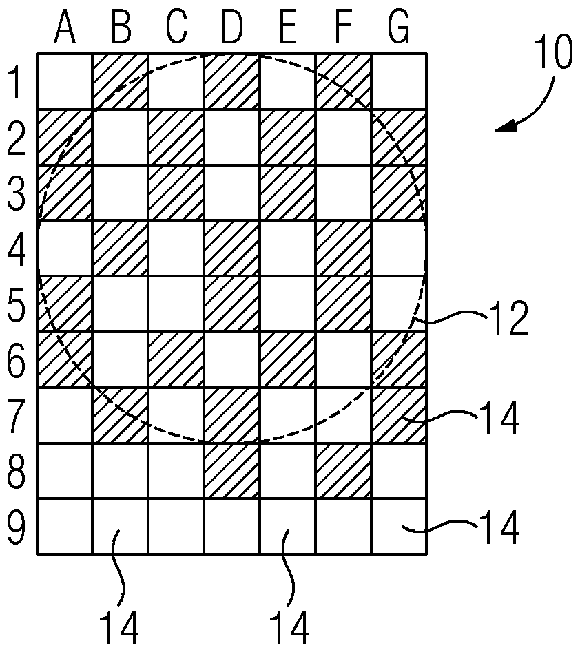
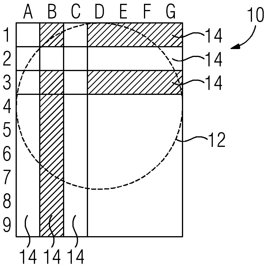
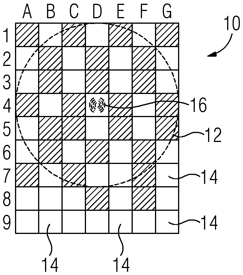
[0026] In order to facilitate the positioning of the motor vehicle via the ground-side inductive charging system, the sensor device 10 is arranged in the region of the ground-side charging coil 12 . The sensor device 10 consists of a pyroelectric film which is divided into individual sensor regions 14 , and not all sensor regions 14 are shown for the sake of clarity. In total, a matrix of 7×9 sensor fields 14 is thus provided.

[0027] A heat source that is activated at the beginning of the charging process is arranged in the area of ​​the induction coil of the vehicle to be charged. Ideally, the heat source is placed in the center of the coil on the vehicle side, since then the measuring range of the position measuring system is maximized. The heat sources can be designed as point radiators, surface radiators or collimated radiators.

[0028] Depending on the position of the vehicle above the ground-side coil 12 , different sensor regions 14 are irradiated with heat sources...


PUM


Abstract

Charging device and method for inductive charging of electrical energy stores. The invention relates to a charging device for the inductive charging of an electric energy store of a motor vehicle, the charging device having a coil on the vehicle side and a coil (12) on the road side, characterized in that the coil (12) on the road side At least one temperature sensor ( 14 ) is arranged in the area of ​​the coil, and at least one heat source is arranged in the area of ​​the vehicle-side coil.

Description

technical field [0001] The invention relates to a charging device for the inductive charging of an electrical energy store and a method for the inductive charging of an electrical energy store. Background technique [0002] During the inductive charging of the vehicle battery, electrical energy is transmitted contactlessly from the coil on the ground side to the coil on the vehicle side. In order to achieve optimum efficiency in the energy transmission, the vehicle must be correctly aligned with the ground-side coil such that the ground-side coil overlaps the vehicle-side coil. [0003] In order to support the driver in the correct positioning of his vehicle, systems are known in which the positioning is checked by communication of a small auxiliary coil. One of the auxiliary coils is integrated as a transmitting coil in the lane-side coil system, and the other auxiliary coil is integrated as a receiving coil in the vehicle-side coil system. Signal transmission between the...

Claims


Application Information

Patent Timeline
Patent Type & Authority Patents(China)
IPC IPC(8): B60L11/18
CPCB60L2240/36B60L53/126B60L53/38Y02T10/70Y02T10/7072Y02T90/12Y02T90/14B60L53/12
Inventor G.巴赫迈尔C.巴赫曼D.伯格曼M.塞里亚克斯R.弗赖塔格M.格尔利希
Owner SIEMENS AG
Why Eureka
Try Eureka