Flash detector for nuclear imaging device

A scintillation detector and nuclear imaging technology, applied in the field of scintillation detectors, can solve the problems of weakened position information of incident rays, scattered scintillation light, no position resolution ability, etc., and achieve good position resolution and cost saving effects

Inactive Publication Date: 2007-07-25
INST OF HIGH ENERGY PHYSICS CHINESE ACAD OF SCI
View PDF5 Cites 0 Cited by
  • Summary
  • Abstract
  • Description
  • Claims
  • Application Information

AI Technical Summary

Problems solved by technology

However, due to the dispersion of scintillation light during the transmission of scintillation light by general light-guiding materials, the position information of incident rays is weakened
Moreover, the general photomultiplier tube has no position resolution ability, so it is difficult to extract the position information of the incident ray from the signal obtained on the anode of a single photomultiplier tube

Method used


Image

  • Flash detector for nuclear imaging device
  • Flash detector for nuclear imaging device
  • Flash detector for nuclear imaging device

Examples


Embodiment Construction

[0027] Preferred embodiments of the present invention will now be described in detail with reference to the accompanying drawings. The same or similar elements appearing in different drawings are denoted by the same reference numerals, and detailed description thereof will be omitted.

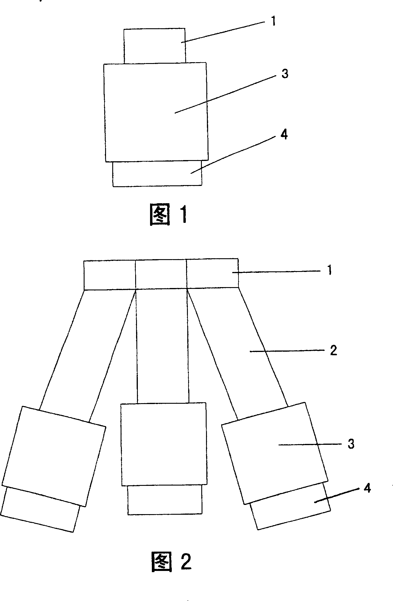
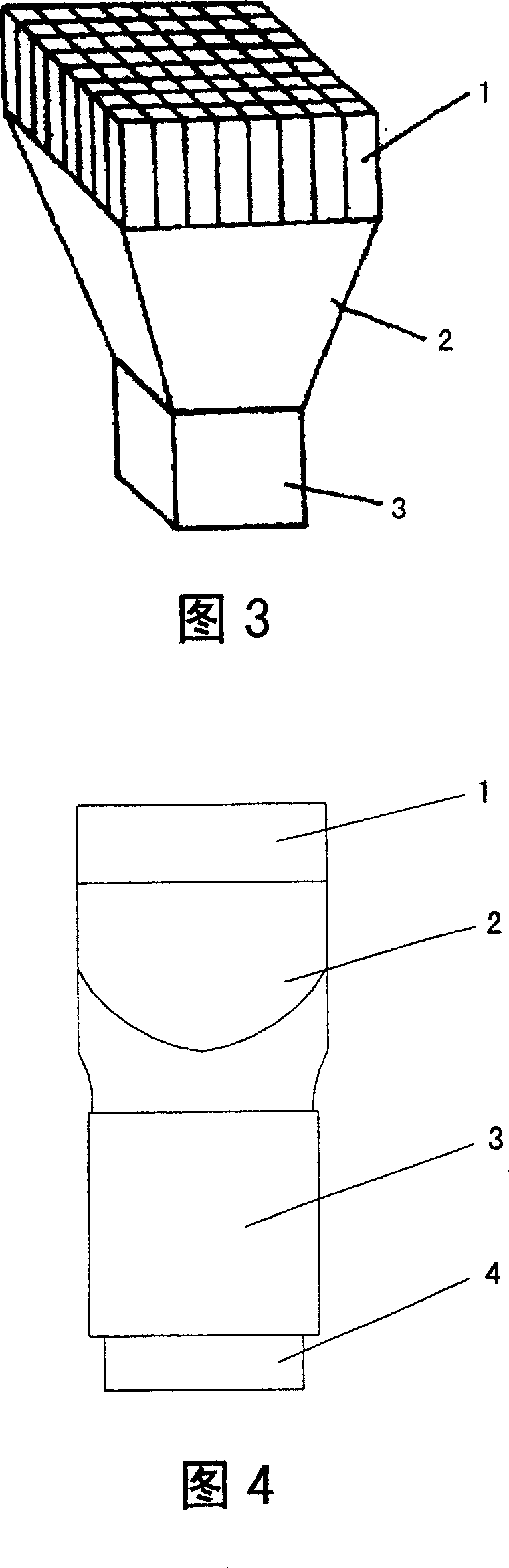
[0028] Please refer to FIG. 4 , which shows the structure of a scintillation detector according to a preferred embodiment of the present invention. The scintillation detector for nuclear imaging is made up of scintillator 1, fiber optic light guide 2 and photomultiplier tube 3, its overall shape is as shown in Figure 5, similarly, tube base and voltage divider circuit 4 are connected below the photomultiplier tube 3 . Wherein, the scintillator 1 used in the detector can be a bulk crystal, or a crystal array composed of multiple crystal units. The shape of the scintillator can be made into different shapes according to the purpose of use, but it is mainly cubic (that is, both the cross-section...


PUM


Abstract

The scintillation detector for nuclear imaging device includes the following components: scintillator, optical fibre light guide and photoelectric multiplier. Said invention also provides the concrete action and structure of the above-mentioned every component, and provides their connection mode.

Description

technical field [0001] The invention relates to a scintillation detector used in a nuclear imaging device, in particular to a position sensitive scintillation detector with good position resolution capability. Background technique [0002] Nuclear imaging is based on detecting the position and energy of radioactive rays, and has been widely used in medical diagnosis, environmental assessment, scientific research and other fields. One of the key components of a nuclear imaging device is the detector. At present, the detectors used for nuclear imaging mainly include gas detectors, scintillation detectors, and semiconductor detectors, among which scintillation detectors are widely used. [0003] A scintillation detector generally consists of a scintillator and a photomultiplier tube. Its working principle is as follows: scintillators are made of materials that can emit scintillation light after receiving radioactive rays, and most of them are scintillation crystals. The shape...

Claims


Application Information

Patent Timeline
Patent Type & Authority Patents(China)
IPC IPC(8): G01T1/208G01T1/20
Inventor 李道武章志明单保慈马创新张天保魏龙
Owner INST OF HIGH ENERGY PHYSICS CHINESE ACAD OF SCI
Why Eureka
Try Eureka