Wireless magnetic-resonance charging device based on array coils

A technology of wireless charging and array coils, applied in circuit devices, electrical components, electromagnetic wave systems, etc., can solve the problems of reduced radiation, low transmission efficiency, and large surrounding radiation, and achieve flexible adjustment, high-efficiency transmission, and uniform electromagnetic field distribution.

Inactive Publication Date: 2014-01-22
WUHAN UNIV
View PDF3 Cites 19 Cited by
  • Summary
  • Abstract
  • Description
  • Claims
  • Application Information

AI Technical Summary

Problems solved by technology

One is that the size of the coil at the receiving end has a greater impact on the received power, and a large current is required to ensure normal charging; the other is that the transmission distance is very short, the transmission efficiency is very low, and it is easily affected by the deviation between the transmitter and receiver coils , the scope of application is greatly limited; the third is that the surrounding radiation is relatively large, which affects the surrounding animals and plants and the normal operation of electronic equipment, etc.
The magnetic resonance

Method used


Image

  • Wireless magnetic-resonance charging device based on array coils
  • Wireless magnetic-resonance charging device based on array coils
  • Wireless magnetic-resonance charging device based on array coils

Examples


Embodiment

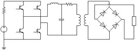
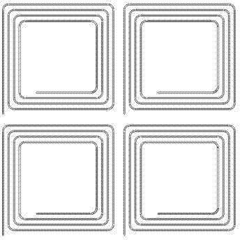
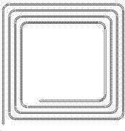
[0027] The present invention discloses several array coil structures for magnetic resonance long-distance wireless charging, and the present invention will be further described below in conjunction with the proposed structures. The transmitting end is a coil sequence unit composed of identical coils, and an alternating magnetic field is generated by applying a high-frequency alternating current to the transmitting coil. The receiver coil is the same coil as one of the transmitter coil trains and receives the transferred energy via an alternating magnetic field and transmits it to the load. Current and voltage feedback and controllers can be introduced into the above system to improve the efficiency of power transfer between the transmitter and receiver.

[0028] The coils are arranged in an array to maximize the use of the area of ​​the transmitting coil. The magnetic flux distribution in space between the transmitting end and the receiving end is uniform. In addition, each ...

Embodiment 2

[0034] Figure 3a is the transmitting end of the triangular helical three-coil array, Figure 3b It is the receiving end of a single triangular helical coil. Others are the same as those in the embodiment, and will not be repeated here.

Embodiment 3

[0036] Figure 4a It is the transmitting end of the circular helical six-coil array, Figure 4b It is the receiving end of a single circular helical coil. Others are the same as those in the embodiment, and will not be repeated here.


PUM


Abstract

The invention relates to a wireless charging device, in particular to a wireless magnetic-resonance charging device based on array coils. The wireless magnetic-resonance charging device comprises a power supply, a control circuit, a driving circuit and a transmitting terminal, which are sequentially connected, and a receiving terminal and an electric energy converting circuit, which are sequentially connected, wherein the transmitting terminal comprises a plurality of spiral coils; the receiving terminal is a spiral coil. The wireless magnetic-resonance charging device has the advantages as follows: 1, different from conventional circular coils, the coils adopting efficient array structures can enable an electromagnetic field to be distributed uniformly to a certain extent; 2, the distribution of the electromagnetic field generated by the efficient array coils compared with conventional coils is more regular; 3, under a certain external environmental condition, the distribution of the efficient array coils can be regulated so as to efficiently transmit electric energy; 4, the transmitting array coils and the receiving array coil can have the same or different structures and can be flexibly regulated.

Description

[0001] technical field [0002] The present invention relates to a wireless charging device, in particular to a magnetic resonance wireless charging device based on an array coil. Background technique [0003] Compared with the charging method of conductor connection, wireless charging is safer and more convenient, and the charging process is less susceptible to interference. Due to the natural grid isolation, the reliability and safety of wireless chargers are greatly improved. The power transmission is carried out through the appropriate distance between the transmitting coil and the receiving coil installed on the device, which can eliminate the inconvenience of short circuits caused by cables, connectors and plugs, and is an autonomous charging system. [0004] Current wireless power charging devices are mainly based on two methods: inductive coupling and magnetic resonance. Inductive coupling has been used in various fields, but it has several disadvantages. One is t...

Claims


Application Information

Patent Timeline
IPC IPC(8): H02J17/00H02J50/12
Inventor 王军华刘开培常辉
Owner WUHAN UNIV
Why Eureka
Try Eureka