Supercharge Your Innovation With Domain-Expert AI Agents!

Stator with concentric type winding

A concentric winding and stator technology, applied in the field of stators, can solve the problems of increased cost, high end loss, and high voltage failure rate, so as to improve life and reliability, increase slot area utilization rate, and reduce end loss Effect

Inactive Publication Date: 2014-01-22
ZHUHAI KAIBANG MOTOR MFR +4
View PDF4 Cites 2 Cited by
  • Summary
  • Abstract
  • Description
  • Claims
  • Application Information

AI Technical Summary

Problems solved by technology

[0005] Traditional motor stator winding forms such as image 3 As shown, when inserting wire or winding wire, enter the wire from the slot, and the winding is divided into inner winding and outer winding. When inserting wire or winding, the adjacent two-phase windings are distributed on the same circle, and one phase winding must cross the other phase winding. , the adjacent two-phase windings overlap in space, resulting in a part or most of the slot area being unusable, and the small coils of the inner and outer windings are distributed in the same winding slot, and it is easier to damage the winding when inserting the wire, resulting in two winding turns The defect rate of space and pressure resistance increases, and the large circle span of the inner and outer windings is too far. In order to meet the requirement that there is enough avoidance space at the position of the iron core slot after the adjacent two-phase windings are embedded, the length of the coils of the two windings is lengthened, that is, The increase in the amount of wire enameled wire increases the difficulty in winding the winding and inserting the wire. The rear end of the embedded winding is high, the end loss is high, the cost increases, and the motor efficiency is low.

Method used


Image

  • Stator with concentric type winding
  • Stator with concentric type winding
  • Stator with concentric type winding

Examples


Embodiment Construction

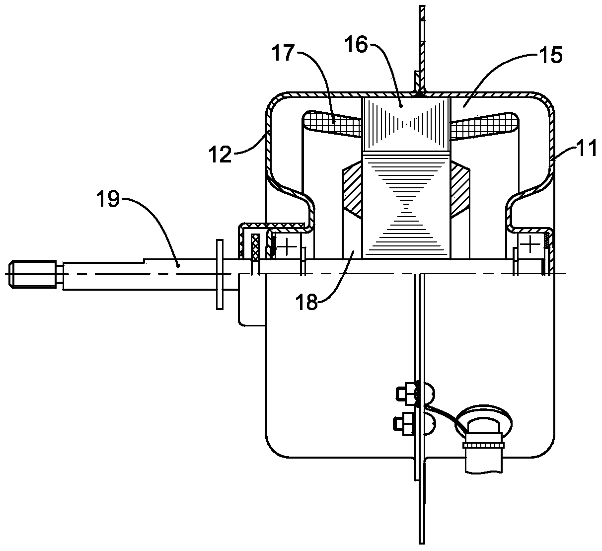
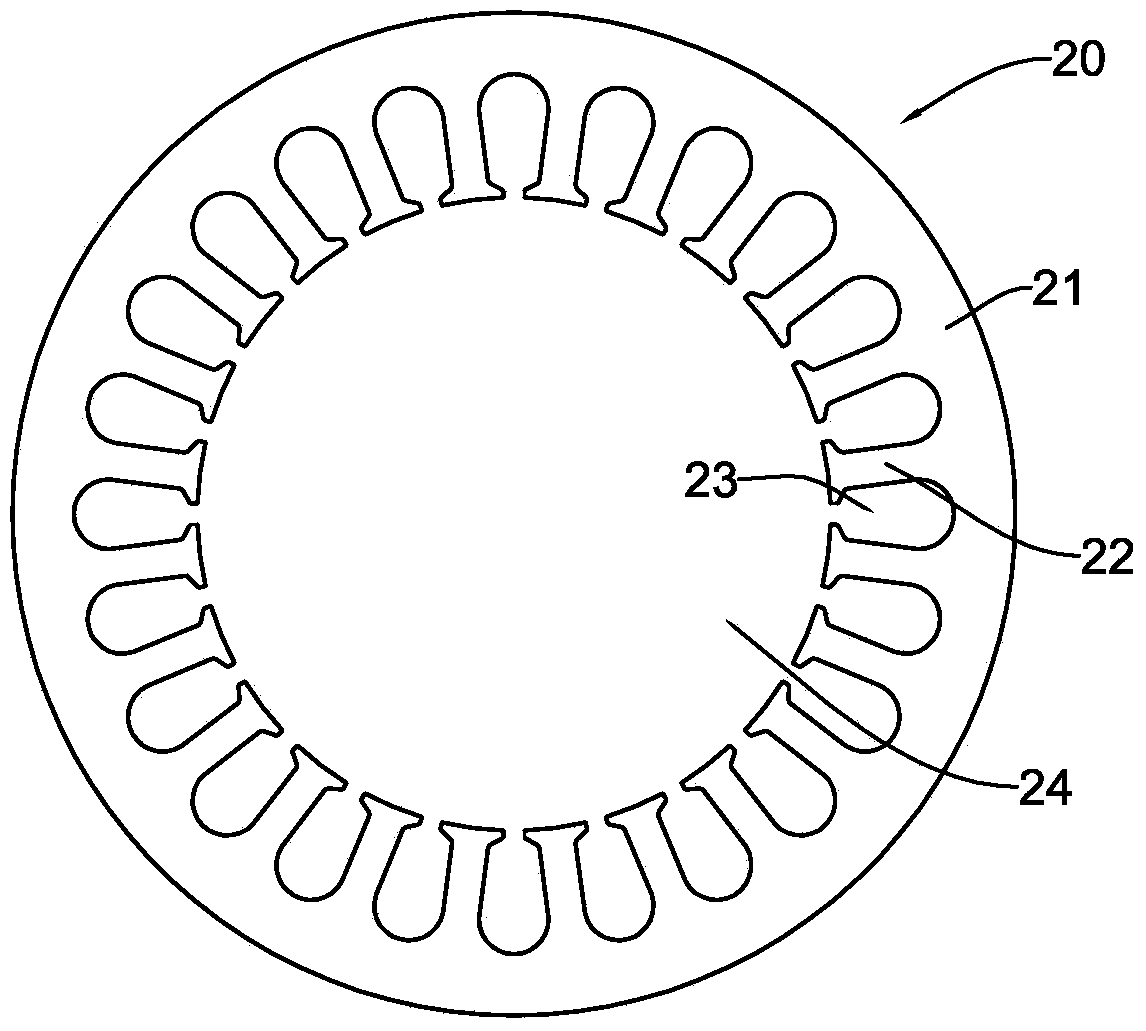
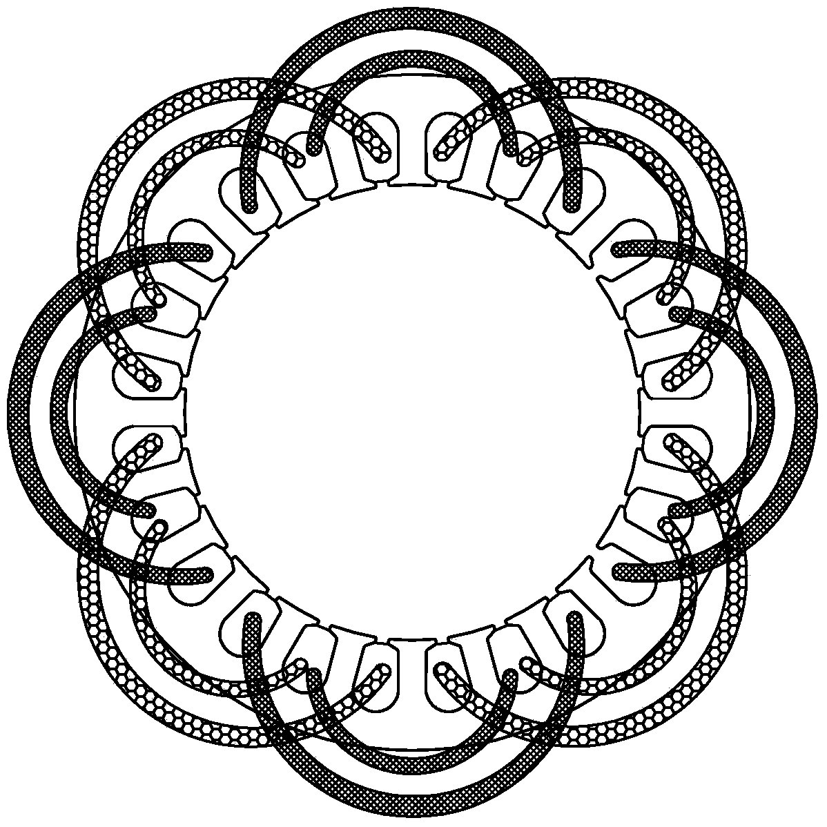
[0020] like Figure 4 As shown, an embodiment of the present invention is a 4-pole 24-slot concentric winding stator, including a stator core 60, an outer coil winding 41 and an inner coil winding 42, wherein the stator core 60 is a yoke separated stator core, It consists of a detachably connected tooth portion 47 and a yoke portion 45 , the annular yoke portion 45 is located on the outer periphery of the tooth portion 47 , and the tooth portion 47 is located inside the yoke portion 45 . A circular hole 43 is provided in the middle of the tooth portion 47 , and the rotor can be installed in the circular hole 43 . The tooth portion 47 can be covered with an insulating sleeve or an injection molded insulating sleeve to prevent the coil winding from contacting the tooth portion 47 . When manufacturing the stator, the coil winding can be directly wound on the tooth part 47 by winding equipment, and then the tooth part 47 wound with the coil winding can be installed in the yoke pa...


PUM


Abstract

The invention provides a stator with a concentric type winding. The stator with the concentric type winding comprises a stator iron core and a coil winding, wherein the tooth part of the stator iron core is detachably connected with the yoke part of the stator iron core, the yoke part is positioned on the periphery of the tooth part, and a round hole is formed in the middle of the tooth part; the tooth part comprises a plurality of straight teeth and bent teeth arrayed in an annular manner, and a winding slot is formed between every two teeth; more than two bent teeth with the same pointing direction are formed between two adjacent straight teeth, and the pointing directions of the bent teeth on the two sides of each straight tooth are opposite. According to the stator with the concentric type winding, the tooth shape of the iron core of an existing stator is optimized, namely the size structure of the winding slots is optimized, the position of the winding is determined by the shape and arrangement sequence of the teeth, the utilization rate of the slot areas of the winding slots is improved, the winding difficulty is reduced, the length of a coil conductor is reduced, the end part loss of the coil of a motor is reduced, the service life and the reliability of the motor are improved, the cost of the motor is reduced, the design is enabled to be more reasonable, the performance of the motor is improved, and the automation degree is high.

Description

technical field [0001] The invention relates to a stator, especially a stator with concentric windings. Background technique [0002] Motors are widely used in various electrical equipment in industrial production and life. The existing motors have a stator and a rotor. The rotor shaft is installed in the rotor and rotates with the rotation of the rotor, thereby outputting power. [0003] see figure 1 Some existing motors have a housing composed of end covers 11 and 12 , a stator 15 and a rotor 18 are installed in the housing, and the stator 15 has a stator core 16 and a coil 17 wound on the stator core 16 . The rotor 18 is installed in the stator 15 and is rotatable relative to the stator 15 . The rotor shaft 19 is installed in the rotor 18 and has an interference fit with the rotor 18 . The rotor shaft 19 rotates driven by the rotor 18 to output power outward. [0004] The stator core 16 is usually formed by laminating multiple stator punches with the same shape, s...

Claims


Application Information

Patent Timeline
IPC IPC(8): H02K1/14H02K1/16
Inventor 苏得喜陈川礼刘伟兵
Owner ZHUHAI KAIBANG MOTOR MFR
Features
  • R&D
  • Intellectual Property
  • Life Sciences
  • Materials
  • Tech Scout
  • Unparalleled Data Quality
  • Higher Quality Content
  • 60% Fewer Hallucinations
Learn More