
Digital signal transmission method and device

A digital signal transmission and signal frame technology, applied in electrical components, transmission systems, etc., can solve the problems of complex signal frame structure, poor frame header synchronization performance, etc., to improve system synchronization performance, without losing flexibility, and simplify frame structure Effect

Active Publication Date: 2015-09-23
SHANGHAI NAT ENG RES CENT OF DIGITAL TELEVISION
View PDF4 Cites 0 Cited by
  • Summary
  • Abstract
  • Description
  • Claims
  • Application Information

AI Technical Summary

Problems solved by technology

[0003] The purpose of the present invention is to provide a digital signal transmission method and device to solve the problem of complex signal frame structure and poor frame header synchronization performance in the existing broadcasting system

Method used

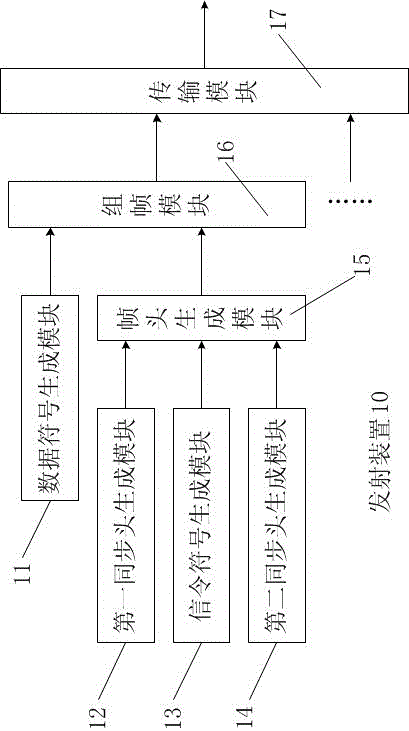

Image

  • Digital signal transmission method and device
  • Digital signal transmission method and device
  • Digital signal transmission method and device

Examples


Embodiment Construction

[0018] The technical solutions of the present invention will be further described below in conjunction with the accompanying drawings and embodiments.

[0019] Such as figure 1 As shown, the present invention first discloses a digital signal transmitting device 10, the core of which is a four-layer structure. According to the sequence of signal frame generation and transmission, the first layer structure is a data symbol generation module 11, a first synchronization header generation module 12, The signaling symbol generation module 13 and the second synchronization header generation module 14 , the second layer structure is the frame header generation module 15 , the third layer structure is the framing module 16 , and the fourth layer structure is the transmission module 17 .

[0020] The overall flow of the transmission method of the present invention is:

[0021] The data symbol generation module 11 divides and converts the information to be transmitted into data symbols....


PUM


Abstract

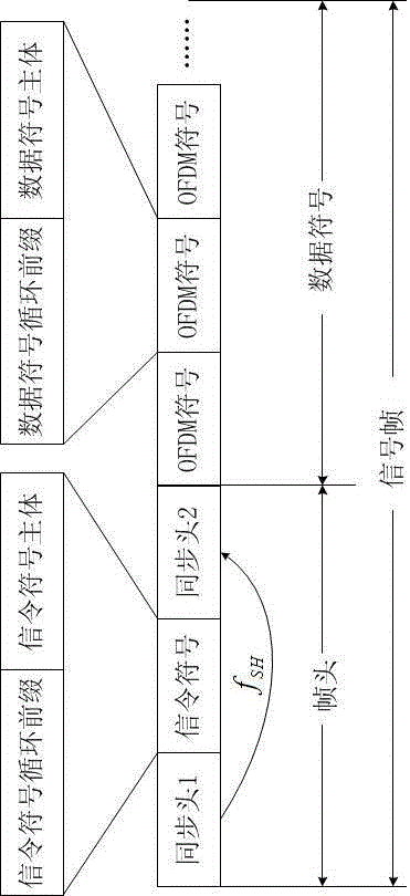
The invention discloses a digital signal transmission method and a digital signal transmission device. The digital signal transmission method comprises the following steps of dividing information to be transmitted and converting to a data symbol; adding a frame header at the front of the digital symbol so as to form a signal frame, wherein the frame header comprises a first synchronous head, a signaling symbol and a second synchronous head, the second synchronous head is a frequency shift sequence of the first synchronous head, the signaling symbol is located between the first synchronous head and the second synchronous head, and the signaling symbol comprises basic signaling information used for demodulating the data symbol; and combining the continuous signal frames to a data stream to transmit. By adopting the technical scheme provided by the invention, the signal frame provided with a novel frame header structure is obtained in a broadcasting system, the frame structure is simplified, and system synchronization performance is improved without losing flexibility.

Description

technical field [0001] The present invention relates to a communication method and device, more specifically, to a digital signal transmitting method and device for a broadcasting system. Background technique [0002] In DVB-T2, a T2 frame includes P1, P2 and data symbols, among which P1 has a "C-A-B" structure, which is not only used for preliminary synchronization, but also used to carry signaling for demodulation of P2. The structure is more complex and the PAPR is higher . In China's terrestrial digital TV standard (GB2006-20600), a signal frame includes PN sequence, system signaling and data symbols. PN sequence does not carry any signaling for demodulation of other parts, but it can be used for system synchronization. However, synchronization The performance is insufficient, and the system signaling design is not flexible enough. Contents of the invention [0003] The object of the present invention is to provide a digital signal transmission method and device to s...

Claims


Application Information

Patent Timeline
Patent Type & Authority Patents(China)
IPC IPC(8): H04B1/04
Inventor 张文军管云峰何大治史毅俊徐胤郭序峰
Owner SHANGHAI NAT ENG RES CENT OF DIGITAL TELEVISION
Learn More