Modular rapidly-formed water-cooling plate

A water-cooled plate, modular technology, applied in the direction of cooling/ventilation/heating transformation, can solve the problems of high welding cost and water-cooled plate leakage, avoid high costs, increase thermal performance, and adjust the effect of flow channel layout

Inactive Publication Date: 2014-01-22
CRRC DALIAN INST CO LTD
View PDF5 Cites 5 Cited by
  • Summary
  • Abstract
  • Description
  • Claims
  • Application Information

AI Technical Summary

Problems solved by technology

[0003] At present, with the rapid development of high power and high integration of electronic components, the heat generated during their work is increasing, and the requirements for water-cooled plates are becoming more and more stringent, and the water-cooled plates in the form of brazing exist to a certain extent. The safety hazard of leakage, and the welding cost is very high, so it is very important to improve the safety of the water cooling plate and reduce the cost

Method used


Image

  • Modular rapidly-formed water-cooling plate
  • Modular rapidly-formed water-cooling plate

Examples


Embodiment 1

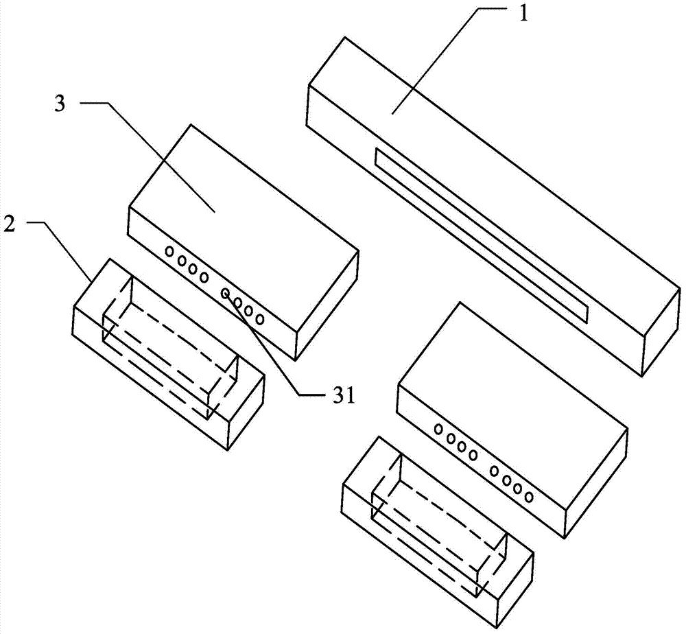
[0022] like figure 1 As shown, a modular rapid prototyping water-cooled plate, according to the given coolant flow rate and the heat generated by electronic power components, after analyzing the thermal resistance, flow resistance and installation space of the water-cooled plate, the main collecting chamber 1 and two main collecting chambers are used. The heat dissipation structure of the cavity 3 and the two collecting chambers 2 matched with the main cavity 3 .

[0023] The main cavity 3 is formed by drawing aluminum, and then the main cavity 3 is processed to the target size. The main cavity 3 is provided with a plurality of flow channels 31 that run through the main cavity 3 and are used for the flow of cooling liquid. The flow channels 31 can be made into at least one of circular, triangular or rectangular cross-sections as required. At least one or more of the flow channels with fins in the flow channel, the inner spiral flow channel with increased longitudinal vortex, ...

Embodiment 2

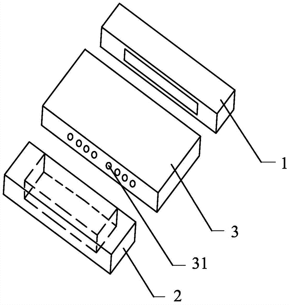
[0026] like figure 2 As shown, a modular rapid prototyping water-cooled plate, according to the given coolant flow rate and the heat generated by electronic power components, after analyzing the thermal resistance, flow resistance and installation space of the water-cooled plate, the main collecting chamber 1 and a main chamber are used Body 3 and a heat dissipation structure form of a collecting chamber 2 matched with the main cavity 3 .

[0027] The main cavity 3 is formed by drawing aluminum, and then the main cavity 3 is processed to the target size. The main cavity 3 is provided with a plurality of flow channels 31 that run through the main cavity 3 and are used for the flow of cooling liquid. The flow channels 31 can be made into at least one of circular, triangular or rectangular cross-sections as required. At least one or more of the flow channels with fins in the flow channel, the inner spiral flow channel with increased longitudinal vortex, or the special-shaped fl...


PUM


Abstract

The invention discloses a modular rapidly-formed water-cooling plate which is characterized by comprising a main collecting chamber, at least one main cavity as well as a collecting chamber matched with the main cavity, wherein a plurality of flow paths which penetrate through the main cavity and are used for flow of a coolant are arranged in the main cavity; a coolant accommodating groove I is formed in one side, which is fixed with the main cavity, of the main collecting chamber, and a coolant accommodating groove II is formed in one side, which is fixed with the main cavity, of the collecting chamber; and the main collecting chamber and the collecting chamber are fixed on two sides of the main cavity respectively through friction stir welding. According to the modular water-cooling plate, the thermal resistance is satisfied, meanwhile, the machining difficulty and the machining cost are reduced, the safety is improved, and the normal operation of a power module is facilitated.

Description

technical field [0001] The invention relates to the technical field of heat exchange, in particular to a modular rapid prototyping water cooling plate. Background technique [0002] In the prior art, the working mode of the water-cooled plate is as follows: the heat generated by the power module is transferred to the outer surface of the main cavity through its installation contact surface in the form of heat conduction, and then the heat is diffused from the outer surface of the main cavity to the main cavity in the form of heat conduction. On the inner surface of the cavity, the heat is finally transferred from the circulating coolant from the water-cooled plate to the external environment by means of convective heat exchange. When the entire system reaches thermal balance, the surface temperature of the main cavity will be maintained at the normal operating temperature of the power module. [0003] At present, with the rapid development of high power and high integration ...

Claims


Application Information

Patent Timeline
Patent Type & Authority Applications(China)
IPC IPC(8): H05K7/20
Inventor 刘俊杰王硕
Owner CRRC DALIAN INST CO LTD
Why Eureka
Try Eureka