
Automatic control valve for pit

A technology of self-control valves and shade wells, applied in waterway systems, water supply devices, buildings, etc., can solve the problems that rubber tubes cannot be removed at will, increase huge costs, and are not suitable for manual dredging, so as to prevent mosquitoes from entering and exiting and breeding, and protect the body Healthy, Visible Results

Inactive Publication Date: 2014-01-29
曹振坤
View PDF1 Cites 2 Cited by
  • Summary
  • Abstract
  • Description
  • Claims
  • Application Information

AI Technical Summary

Problems solved by technology

The existing problems of this technology are: 1. After the upper end of the rubber check valve is fixed, when the elastic force of the lower inclined wall and the side wall is used for sealing, its implementation is only suitable for rectangular wellheads and not for circular wellheads.
Therefore, the large resilience and the problem that the rubber tube cannot be removed at will bring troubles to manual dredging
4. Rectangular rubber check valves will have aging problems when they are exposed to the air, especially in harsh environments. The aging will inevitably be accelerated due to high temperature, rain and corrosion. Regular replacement will inevitably increase huge costs.
Therefore, the application cannot be effectively implemented on a large scale for a long time

Method used


Image

  • Automatic control valve for pit
  • Automatic control valve for pit
  • Automatic control valve for pit

Examples


Embodiment 1

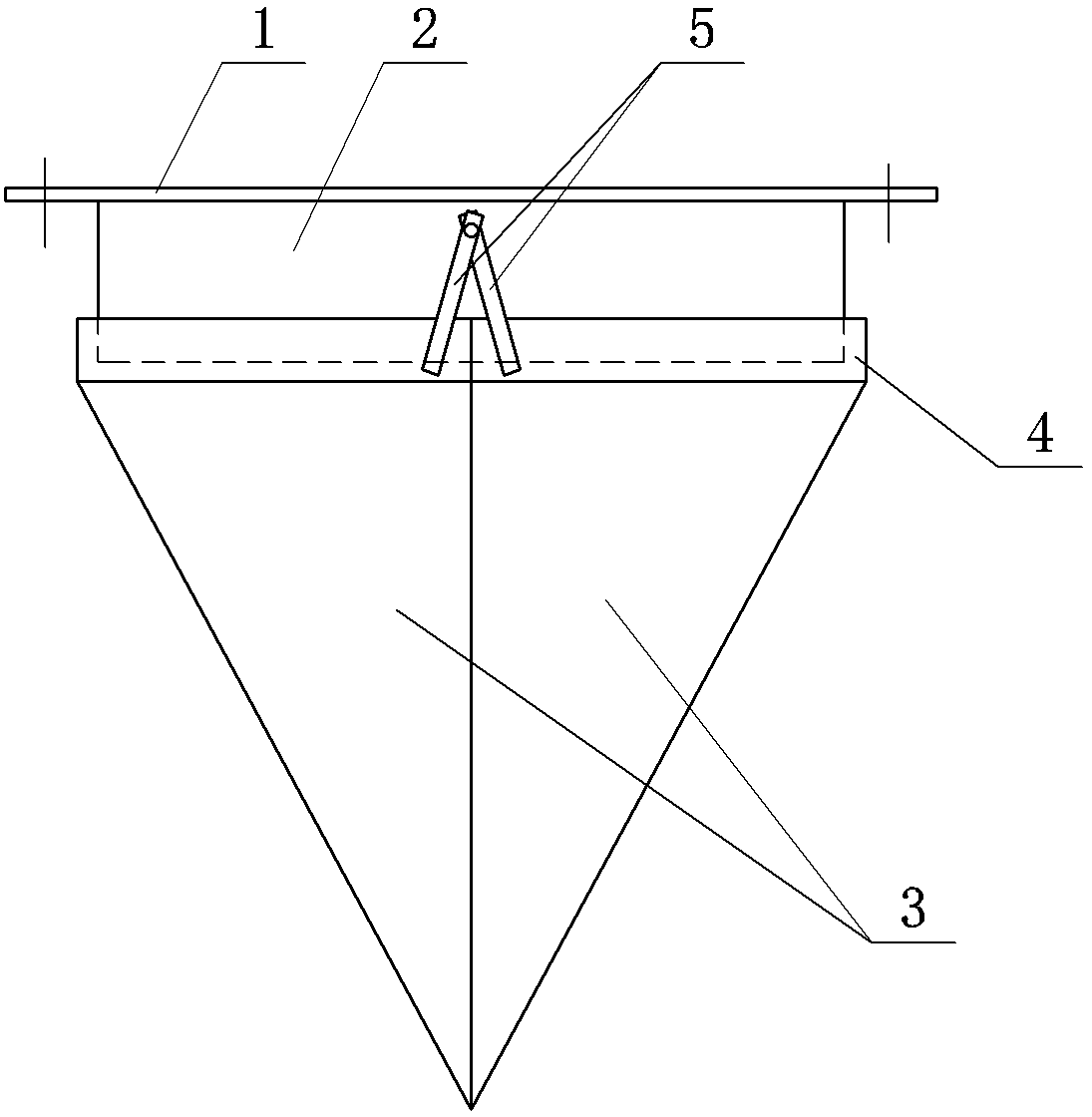
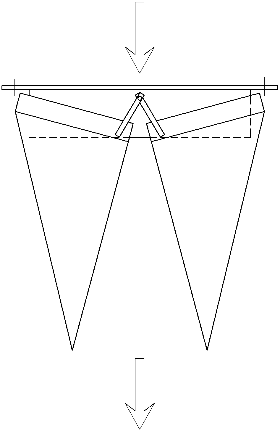
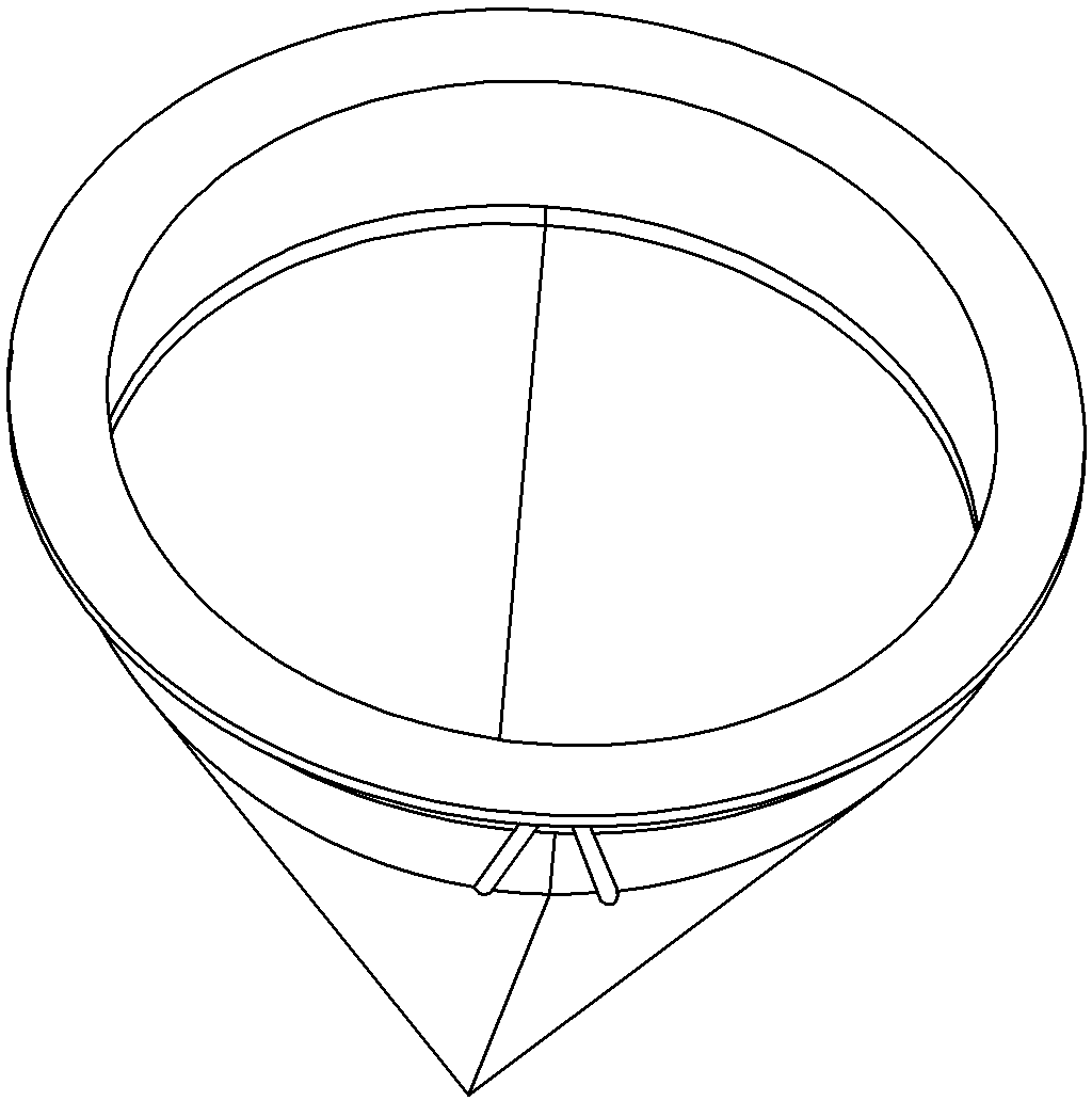
[0016] Embodiment 1: A self-control valve for a yin well, the upper end of which is a fixed cylindrical tube, and the lower end is a group of combined conical tubes that can be expanded. see figure 1 , figure 2 , image 3 and Figure 4 , The upper end of the cylindrical pipe 2 is also provided with a flanging 1, and the flanging 1 is used for matching installation or fixing with the head of the well. The combined conical tube includes two symmetrical conical pieces 3 on the left and right, and the two conical pieces 3 on the left and right form a sealed conical structure after buckling. Connecting rods 5 are respectively fixed on both sides of the upper ends of the left and right two conical pieces 3, and the upper ends of the connecting rods (pieces) 5 are hinged to the outer wall of the cylindrical tube 2 through a pin shaft. The two conical sheets 3 are made of flexible material, such as rubber. The combined cylindrical outer casing 4 is arranged on the upper end of t...

Embodiment 2

[0017] Example 2: see figure 1 and figure 2 , the content is basically the same as that of Example 1, and the similarities will not be repeated. The difference is that the two cones 3 are made of hard material, and the edges of the hard material are provided with a flexible sealing layer, such as stainless steel or aluminum alloy or engineering plastics. Rubber sealing stripe.

Embodiment 3

[0018] Embodiment 3: see figure 1 and figure 2 , the content is basically the same as that of Example 1, and the similarities will not be repeated. The difference is: in order to increase the binding force between the two conical sheets 3, a counterweight can also be arranged on each conical sheet.


PUM


Abstract

The invention discloses an automatic control valve for a pit. The automatic control valve comprises a column tube and a combined taper tube, the combined taper tube comprises a left taper piece and a right taper piece which are symmetric, connecting rods are fixed to two sides of the upper ends of the left taper piece and the right taper piece, and the upper ends of the connecting rods are hinged onto the outer side wall of the column tube through pins. The automatic control valve is suitable for transforming an existing pit opening in a dedicated manner, mosquitoes are prevented from entering and exiting the pit and breeding, dirty air and odor are blocked, a drainage function is unaffected, and fine social effects for protecting fitness of people, purifying urban air pollution and keeping environmental hygiene are achieved. The automatic control valve for the pit is simple in structure, durable in use and low in cost, can be directly used based on original facilities, and is convenient to mount and remarkable in inlet water automatic-opening and water exhaust automatic-closing effect.

Description

technical field [0001] The invention relates to the technical field of municipal renovation, in particular to a self-control valve for a well that can be automatically opened and closed. Background technique [0002] Urban sewers, also known as stinky sewers, often stagnate sewage, garbage, etc. inside, which has an unpleasant smell and is also a breeding ground for many harmful bacteria and viruses. Although the manhole cover is provided, it still maintains the same holes or gaps as the ground. When some manhole covers are often damaged and are not replaced in time, the dirty smell is leaked, and harmful germs are spread outwards, endangering people's health. Especially in hot summer, a large amount of dirty gas and bad smell come out from the shade well, causing air pollution and destroying environmental sanitation. The sewer is also the main place for the overwintering and breeding of pests and mosquitoes. The mouth of the shady well is the only passage for mosquitoes t...

Claims


Application Information

Patent Timeline
IPC IPC(8): E03F7/02
Inventor 曹振坤
Owner 曹振坤
Learn More