Supercharge Your Innovation With Domain-Expert AI Agents!

Scroll expander

An expander and scroll technology, applied in the field of scroll expanders, can solve problems such as deterioration

Inactive Publication Date: 2014-01-29
TOYOTA IND CORP
View PDF8 Cites 0 Cited by
  • Summary
  • Abstract
  • Description
  • Claims
  • Application Information

AI Technical Summary

Problems solved by technology

Thus, the spool 94 and the spring 95, which are constituent parts forming the actuator, are exposed to working fluid having a high temperature and high pressure, so that the spool 94 and the spring 95 are likely to deteriorate due to the working fluid having a high temperature and high pressure.

Method used


Image

  • Scroll expander
  • Scroll expander
  • Scroll expander

Examples


Embodiment Construction

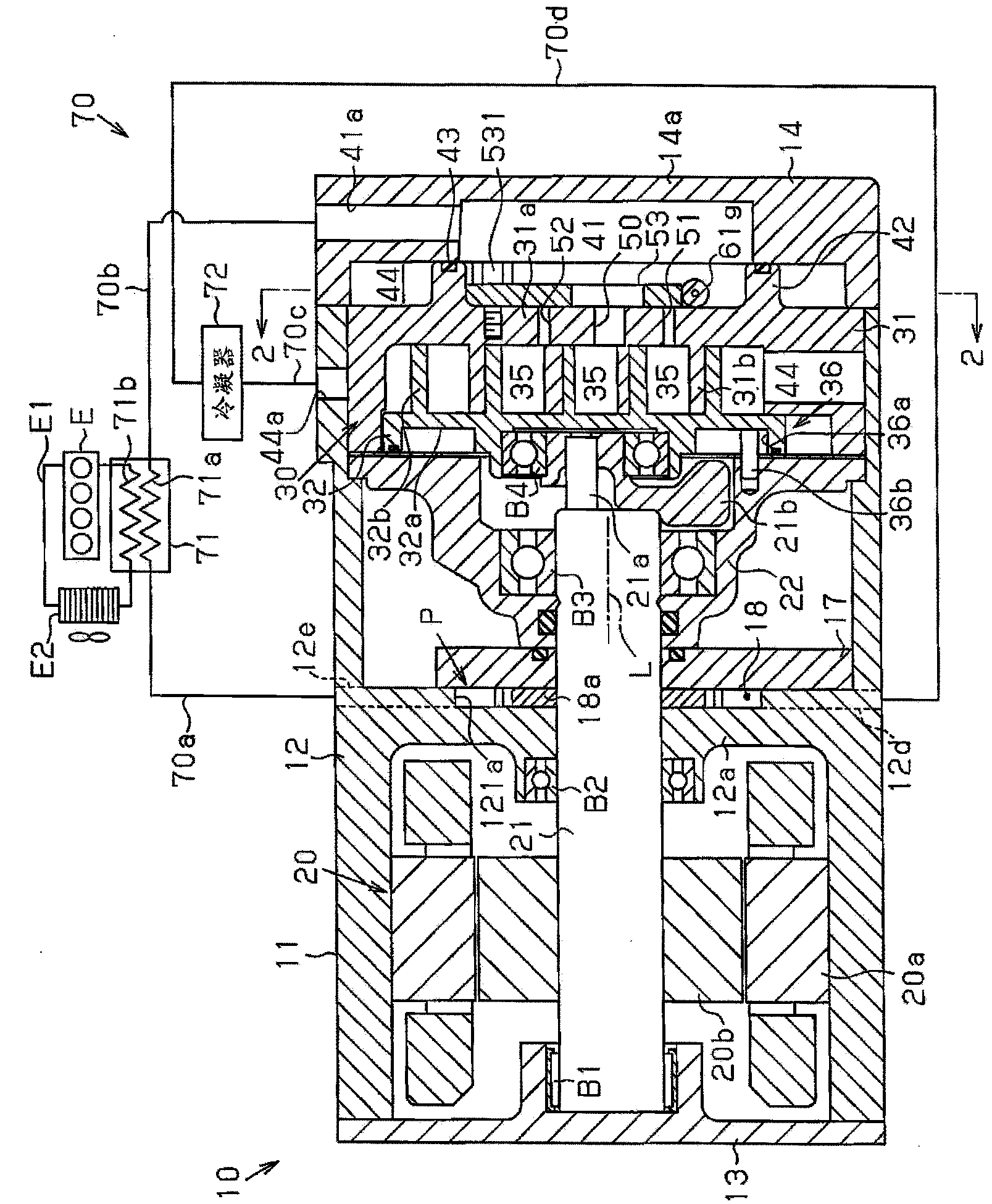
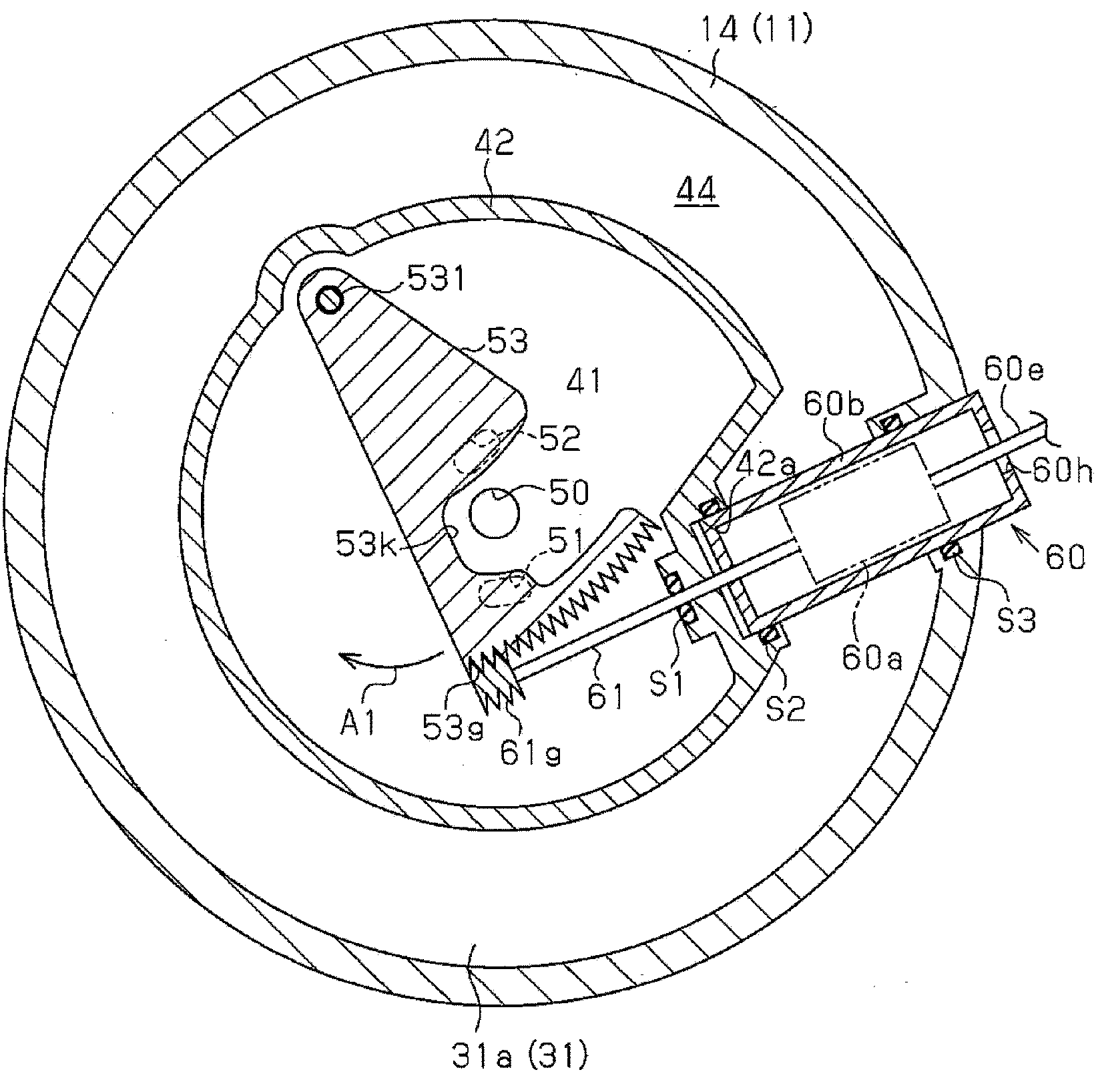
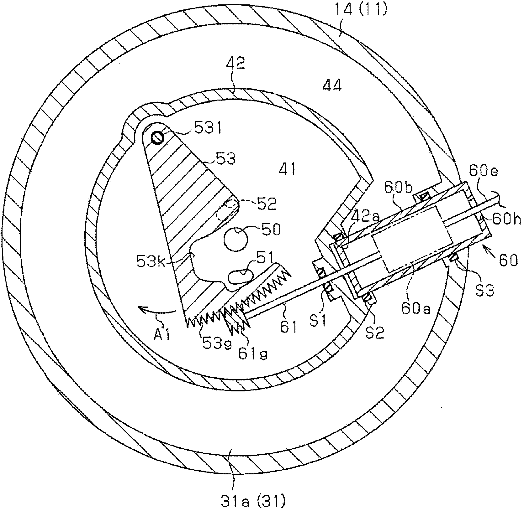
[0019] In the following, reference will be made to Figure 1 to Figure 4 A complex fluid machine 10 to be installed in a Rankine cycle system 70 according to one embodiment of the present invention is described.

[0020] Such as figure 1 As shown, the complex fluid machine 10 includes a housing 11 . The housing 11 is composed of a cylindrical central housing member 12, a plate-shaped front housing member 13, and a rear housing member 14, wherein the plate-shaped front housing member 13 is connected to one end of the central housing member 12, and the rear housing member 14 is The housing member 14 is shaped as a tube having a closed end connected to the other end of the central housing member 12 . A partition wall 12 a is formed on the inner peripheral surface of the center case member 12 . The motor generator 20 is housed in a space defined by the inner peripheral surface of the center case member 12 , the partition wall 12 a , and the front case member 13 . The motor ge...


PUM


Abstract

A scroll expander includes a housing, a main port, a high-pressure chamber, an operation chamber, a low-pressure chamber, a subport, a valve portion, an actuator, and a drive shaft. The high-pressure and low-pressure chambers are separated by a partition wall. The main port draws working fluid in the high-pressure chamber into the operation chamber. The subport introduces the working fluid from the high-pressure chamber to the operation chamber so that the volume of the working fluid in the operation chamber is variable. The valve portion selectively opens and closes the subport. The actuator is arranged in the low-pressure chamber. The drive shaft extends through the partition wall and connects the actuator and the valve portion with each other. When the drive shaft is actuated by the actuator, the subport is selectively opened and closed by the valve portion.

Description

technical field [0001] This invention relates to scroll expanders. Background technique [0002] For example, Japanese Laid-Open Patent Publication No. 2005-30386 discloses this type of scroll expander. The scroll expander includes an expander portion composed of two spiral scrolls, namely, a fixed scroll and an orbiting scroll engaged with each other. An operation chamber (expansion chamber) is defined between the movable scroll and the fixed scroll. The volume of the operating chamber changes according to the orbiting motion of the movable scroll. A suction port (main port) is formed at the central portion of the casing of the expander section. [0003] The working fluid partially discharged to the heat exchanger by the pump gains heat in the heat exchanger to have high temperature and high pressure, and is then sucked into the operation chamber via the suction port to expand. The working fluid is delivered to the peripheral portion while causing the orbiting scroll to...

Claims


Application Information

Patent Timeline
Patent Type & Authority Applications(China)
IPC IPC(8): F01C1/02F01C20/24
CPCF01C1/0215F04C2240/811F01C1/0261F04C2240/30F01C2021/1625F04C23/02F01C20/14
Inventor 森英文井口雅夫榎岛史修田丸耕二郎
Owner TOYOTA IND CORP
Features
  • R&D
  • Intellectual Property
  • Life Sciences
  • Materials
  • Tech Scout
  • Unparalleled Data Quality
  • Higher Quality Content
  • 60% Fewer Hallucinations
Learn More