Multi-level flywheel body oiling machine

An oil injection machine and flywheel technology, which is applied in the direction of mechanical equipment, engine components, engine lubrication, etc., can solve the problems of low work efficiency, uneven oil injection, high labor intensity, etc., and achieve the effect of high speed and good oil injection effect.

Inactive Publication Date: 2014-01-29
YANCHENG INST OF TECH
View PDF6 Cites 5 Cited by
  • Summary
  • Abstract
  • Description
  • Claims
  • Application Information

AI Technical Summary

Problems solved by technology

The current oil injection method is to manually squeeze the injection gun along the gap between the inner and outer rings of the body. Its disadvantages are low work efficiency and high labor intensity;

Method used


Image

  • Multi-level flywheel body oiling machine
  • Multi-level flywheel body oiling machine
  • Multi-level flywheel body oiling machine

Examples


Embodiment Construction

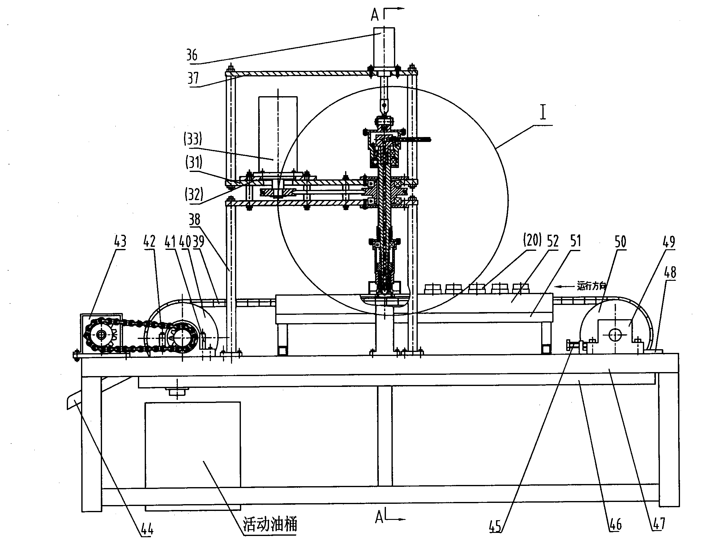
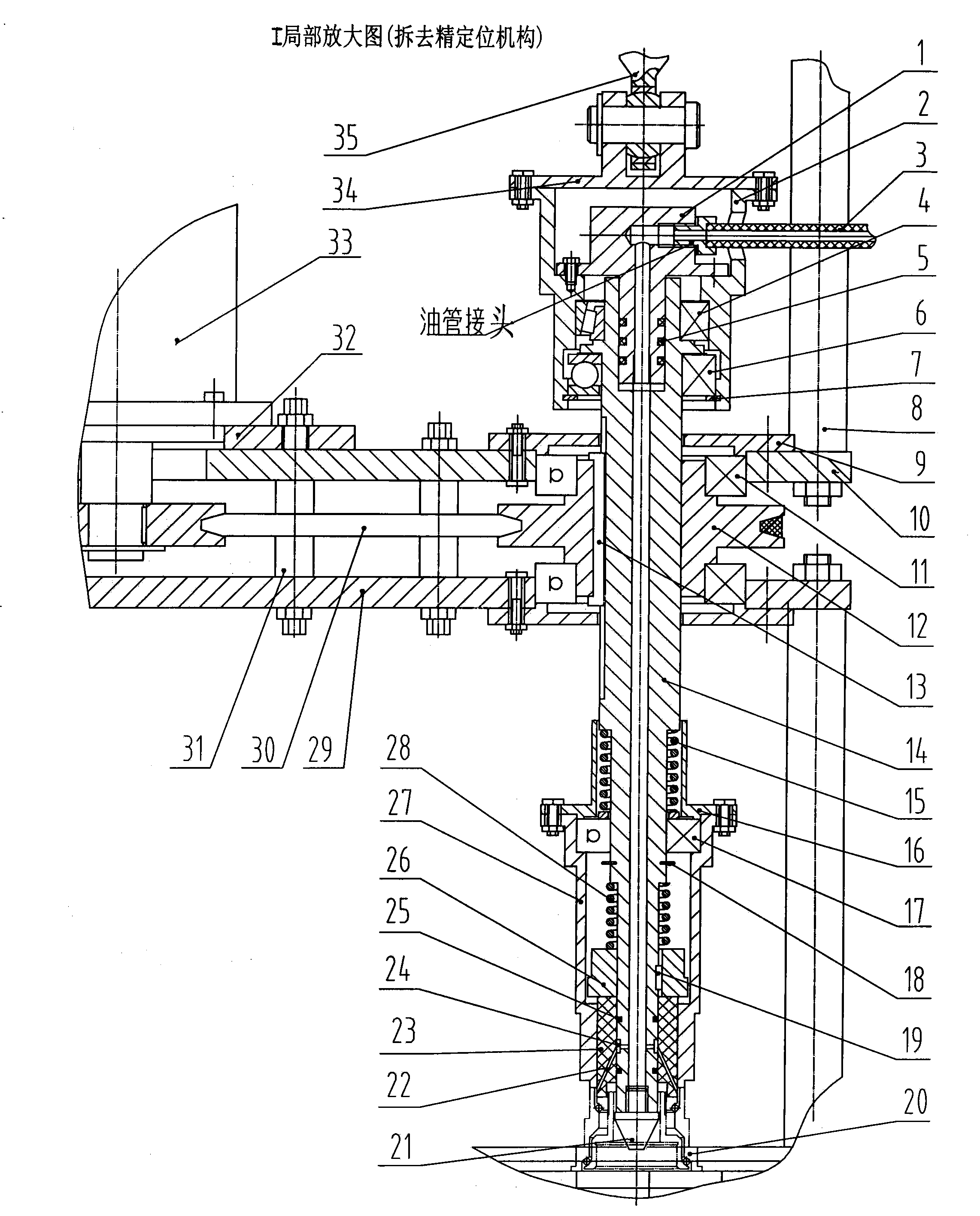
[0015] Below in conjunction with accompanying drawing, the present invention will be described in further detail, as figure 2 Shown, the present invention mainly is made up of frame 47, conveyor belt mechanism, positioning mechanism and oiling rod parts. like figure 2 , Figure 4 Shown, conveyor belt mechanism comprises speed-regulating motor 43, conveyor belt 39, driving wheel 40, tail wheel 50, limit plate 52, supporting bar 57 and oil pan 46 etc., and its driving wheel 40 uses speed-regulating motor 43 to pass chain 42 Drive, the driving wheel 40 drives the conveyor belt 39 to run; the tail wheel bearing seat 49 is connected with the fixed slideway 48 on the frame, and the tension can be adjusted by the screw rod 45; To ensure that the conveyor belt 39 is always kept level during operation; fixedly install limit plates 52 on both sides of the working surface of the conveyor belt 39, so that the flywheel body runs along the fixed track; a fixed oil pan 46 is provided bel...


PUM


Abstract

The invention discloses a multi-level flywheel body oiling machine and relates to bicycle flywheel manufacturing equipment. The multi-level flywheel body oiling machine mainly comprises a machine frame, a conveying belt mechanism, a locating mechanism and an oiling rod part. A supporting strip is fixedly arranged on the lower side of a conveying belt working face. Limiting plates are fixedly arranged on the two sides of the conveying belt working face. Precision locating is carried out through an air cylinder, a workpiece fork and a stopping block combination piece. A large spring, a bearing end cover, a bearing, a blocking ring, a small spring, a transmission block, a pressing injection head and an outer sleeve are arranged on the lower portion of the oiling rod in sequence. The air cylinder drives the oiling rod part through the knuckle bearing to achieve up-down moving. A motor is used for driving through a V-shaped belt and a sliding key to achieve rotating moving of the oiling rod part. During working, a flywheel body moves forward in an intermittence mode on a conveying belt, the oiling rod part moves correspondingly, and hydraulic oil enters a flywheel body inner cavity through an upper end cover, an oiling rod and an inner hole of the pressing injection head to achieve oiling. The multi-level flywheel body oiling machine is good in oiling effect and high in speed, and the problem that currently, no such equipment exists is solved.

Description

technical field [0001] The invention relates to bicycle flywheel manufacturing equipment, in particular to a multi-stage flywheel body oiling machine. Background technique [0002] The multi-stage flywheel body is the main part of the multi-stage flywheel of the variable speed bicycle. It is mainly composed of a spiral ring, an inner ring, an outer ring and steel balls. The outer ring cooperates with a plurality of sprockets with different numbers of teeth to form a multi-stage flywheel. After the multi-stage flywheel body is manufactured and assembled, lubricating oil (or grease) needs to be injected between the inner and outer rings and then packaged for delivery to prevent rust. The current method of oil injection is to manually squeeze and inject along the gap between the inner and outer rings of the body with an injection gun. Its disadvantages are low work efficiency and high labor intensity; [0003] purpose of invention [0004] The object of the present invention ...

Claims


Application Information

Patent Timeline
Patent Type & Authority Applications(China)
IPC IPC(8): F16N7/38
Inventor 曹兆熊曹灿洪思文李谨刘必武
Owner YANCHENG INST OF TECH
Why Eureka
Try Eureka