Integrated assembling mechanism of box oil injector

An assembly mechanism and lubricator technology, which is applied to assembly machines, metal processing equipment, manufacturing tools, etc., can solve the problems of low yield rate, labor-intensive labor, low efficiency of lubricator assembly, etc., to achieve convenient operation and improve yield rate , to achieve the effect of position change and precise docking assembly

Active Publication Date: 2017-03-22
安徽长吉汽车科技有限公司
View PDF5 Cites 2 Cited by
  • Summary
  • Abstract
  • Description
  • Claims
  • Application Information

AI Technical Summary

Problems solved by technology

[0002] like Figure 5 As shown, most of the oilers are made up of the box body carrying the case cover 10, the gear shaft 73 installed by the copper 75 cover on the case cover 10, the gear 72 installed by the gear shaft 71 and the cover plate 74 on the case cover 10 , in order to improve the rigidity of the load-bearing gearbox, most of the existing gearboxes use an integrated box, so the assembled box will be used in the assembly process of the lubricator, and then the gear shaft and the gear shaft will be assembled on the box. For gears, in order to ensure that the gear shaft and the gear shaft mesh with each other, most of the existing assembly needs manual adjustment, and the whole assembly is also semi-automatic assembly equipment, which consumes a lot of manpower and requires multiple handling. The assembly efficiency is low, and the yield rate is not high

Method used


Image

  • Integrated assembling mechanism of box oil injector
  • Integrated assembling mechanism of box oil injector
  • Integrated assembling mechanism of box oil injector

Examples


Embodiment Construction

[0035] In order to enable those skilled in the art to better understand the technical solution of the present invention, the present invention will be described in detail below in conjunction with the accompanying drawings. The description in this part is only exemplary and explanatory, and should not have any limiting effect on the protection scope of the present invention. .

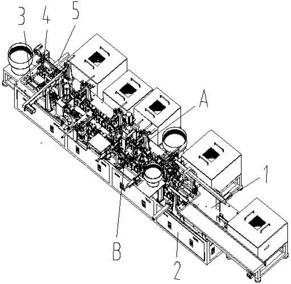
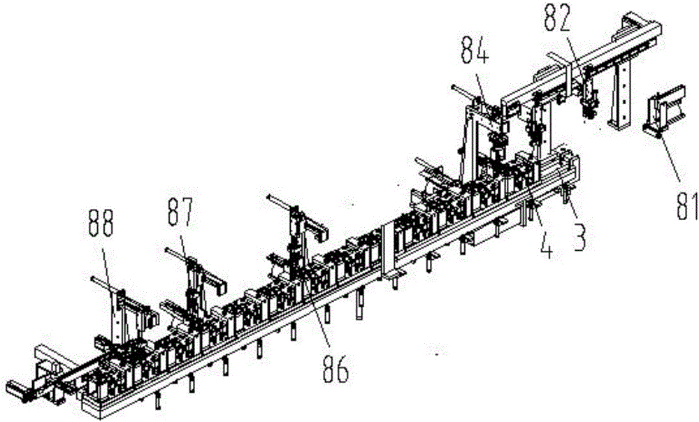
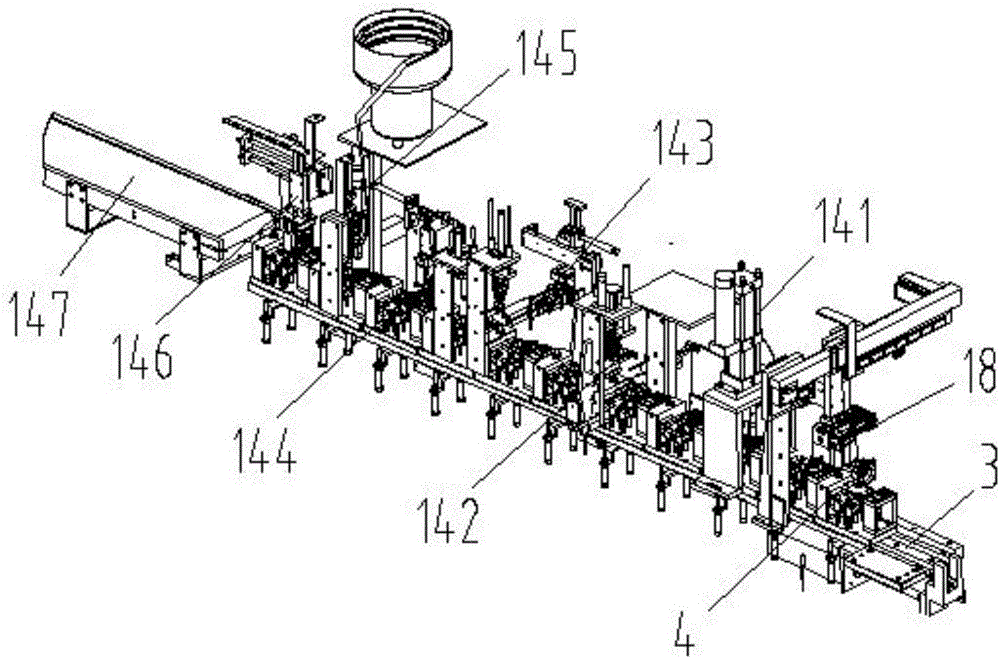
[0036] Such as Figure 1-Figure 14 As shown, the specific structure of the present invention is: an assembly mechanism of an integrated box oiler, which includes a frame 1 and a matching control box 2, and the frame 1 is provided with two parallel and opposite conveying directions. The conveying device 3, the conveying device 3 is provided with a conveying carrier 4, and is switched on the two conveying devices 3 through the transposition cylinder 5 arranged on the frame 1, and the described conveying device 4 includes a conveying carrier seat 76, the middle part of the conveying material seat 76 is a...


PUM


Abstract

The invention relates to an integrated assembling mechanism of a box oil injector. The integrated assembling mechanism of the box oil injector comprises a rack and a matched control box, wherein two conveying devices are arranged on the rack; a conveying carrier is arranged on each conveying device; a transposition cylinder arranged on the rack is switched on the two conveying devices; each conveying carrier comprises a conveying carrying seat; an assembling carrier is arranged in the middle of each conveying carrying seat; a gear shaft placing carrier and a cover plate placing carrier are respectively arranged on two sides of each conveying carrying seat; the conveying device on the rear side is matched with a gear shaft feeding manipulator, a cover plate feeding device, a gear shaft feeding device, a gear feeding device and a copper cover feeding device; and the upper part of the conveying device on the front side is matched with a box transferring device, a copper cover riveting device, a gear shaft oil injection device, a gear shaft assembling device, a cover plate assembling device, a bolt locking device and a discharging manipulator. By the integrated assembling mechanism of the box oil injector, a gear shaft can be accurately engaged with a gear during followed-up assembling, integrated automatic accurate assembling is realized, and the assembling efficiency and the yield are greatly improved.

Description

technical field [0001] The invention relates to the field of processing equipment for lubricators, in particular to an assembly mechanism for an integrated box lubricator. Background technique [0002] Such as Figure 5 As shown, most of the oilers are made up of the box body carrying the case cover 10, the gear shaft 73 installed by the copper 75 cover on the case cover 10, the gear 72 installed by the gear shaft 71 and the cover plate 74 on the case cover 10 , in order to improve the rigidity of the load-bearing gearbox, most of the existing gearboxes use an integrated box, so the assembled box will be used in the assembly process of the lubricator, and then the gear shaft and the gear shaft will be assembled on the box. For gears, in order to ensure that the gear shaft and the gear shaft mesh with each other, most of the existing assembly needs manual adjustment, and the whole assembly is also semi-automatic assembly equipment, which consumes a lot of manpower and require...

Claims


Application Information

Patent Timeline
Patent Type & Authority Applications(China)
IPC IPC(8): B23P21/00
CPCB23P21/004B23P21/008
Inventor 白云曾波李川
Owner 安徽长吉汽车科技有限公司
Why Eureka
Try Eureka