
Electric pump for automobile drive-by-wire braking system

A technology of electric pumps and automobile lines, applied in the direction of brake transmissions, brakes, vehicle components, etc., can solve the problems of small volume of high-pressure brake fluid, fast wear of plunger pumps, low efficiency of high-pressure brake fluid, etc., and achieve reduction The effect of building pressure stroke, reliable operation and improving service life

Active Publication Date: 2017-09-01
JILIN DONGGUANG AOWEI AUTOMOBILE BRAKE SYST
View PDF14 Cites 3 Cited by
  • Summary
  • Abstract
  • Description
  • Claims
  • Application Information

AI Technical Summary

Problems solved by technology

[0004] The invention provides an electric pump for an automobile brake-by-wire system to solve the problem that the volume of high-pressure brake fluid provided by the existing hydraulic pump in a single cycle is small, the amount of brake fluid sucked in each working cycle is small, and the efficiency of outputting high-pressure brake fluid is low. Low, the plunger pump wears quickly, and the problem of service life

Method used


Image

  • Electric pump for automobile drive-by-wire braking system
  • Electric pump for automobile drive-by-wire braking system
  • Electric pump for automobile drive-by-wire braking system

Examples


Embodiment Construction

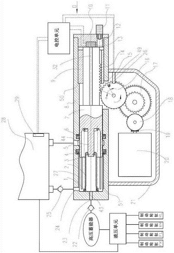
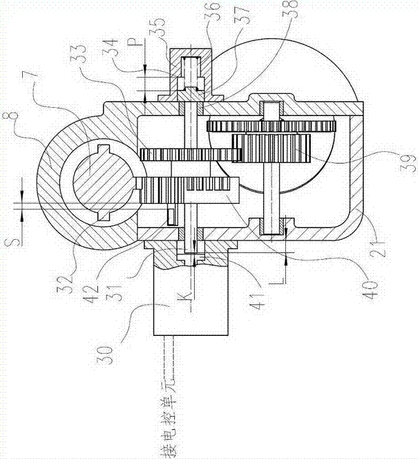
[0014]The guide sleeve 9 has an interference fit with the inner hole of the cylinder body 8, and one axial end is in contact with the limit step 50 of the inner hole of the cylinder body 8. The inner hole of the guide sleeve 9 is a cylindrical surface, and there are axial guide rail grooves 47 symmetrically on both sides of the cylindrical surface. There is an axial rack through groove 48 at the bottom of the cylindrical surface. One end of the piston 7 is a sealing cylindrical surface, and the other end is a guiding part. The diameter of the sealing cylindrical surface is larger than the diameter of the guiding part. There are bar-shaped protruding guide rails 32 symmetrically on both sides of the cylindrical surface in the axial direction, and a rack 14 in the bottom axial direction. The sealing cylindrical surface of the piston 7 is in clearance fit with the main hole of the cylinder body 8, and the guide part is in clearance fit with the cylindrical surface of the inner hole...


PUM


Abstract

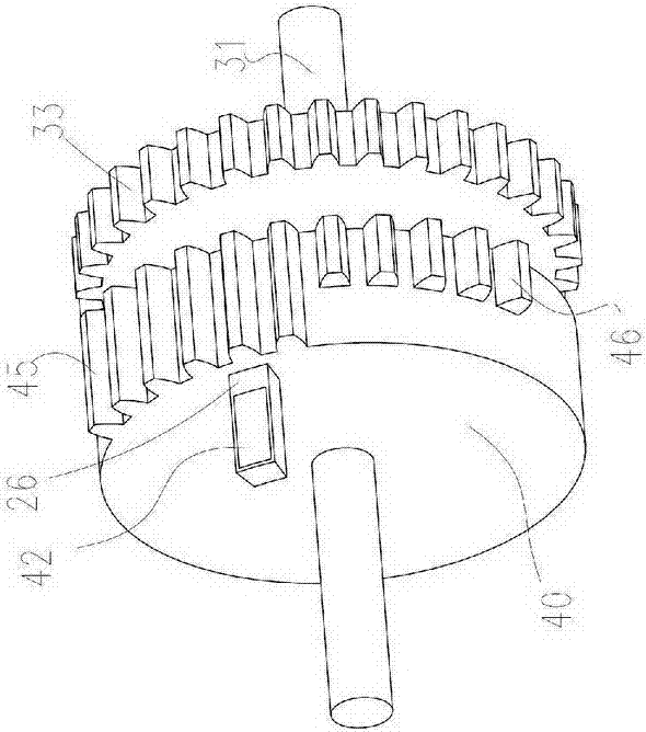
The invention relates to an electric pump for an automobile drive-by-wire braking system and belongs to automobile industries. The electric pump for the automobile drive-by-wire braking system is applied into the automobile drive-by-wire braking system. A guide sleeve is matched with a cylinder body inner hole in an interference mode, one axial end of the guide sleeve makes contact with a limiting step of the cylinder body inner hole, and the surface of a guide sleeve inner hole is a cylindrical surface; the two sides of the cylindrical surface are symmetrically provided with axial guide rail straight grooves, an axial rack straight groove is formed in the bottom of the cylindrical surface, and the diameter of a sealing cylindrical surface is larger than that of a guiding part; a secondary packing cup is sleeved with the sealing cylindrical surface of a piston, strip-shaped protruded guide rails are symmetrically arranged on the two axial sides of a cylindrical surface of the guiding part, and racks are arranged at the bottom of the cylindrical surface of the guiding part in the axial direction; and the sealing cylindrical surface of the piston is matched with a cylinder body primary hole in an interval mode, the guiding part is matched with the cylindrical surface of the guide sleeve inner hole in the interval mode, and the guide rail straight grooves are matched with the guide rails in the interval mode. The electric pump for the automobile drive-by-wire braking system has the advantages that the structure is novel, the number of teeth, engaged with the racks, of transposition gear drive wheels is automatically switched under a low-temperature state so that the pressure-building stroke of the piston can be reduced, return stroke time of the piston is increased, timely supplement of braking fluid at a low temperature is facilitated, and the reliable work of the electric pump under the low-temperature state is ensured.

Description

technical field [0001] The invention belongs to the automobile industry and is applied to the automobile wire control braking system. Background technique [0002] With the development of automobile technology, new energy vehicles and smart driving vehicles have become the main direction of automobile development. Most of these two types of vehicles use brake-by-wire systems. When new energy vehicles perform braking energy recovery, the brake-by-wire system needs a high-pressure hydraulic source to provide high-pressure brake fluid at the desired pressure, which coordinates with regenerative braking to meet the driver's braking needs; when intelligent driving vehicles actively intervene in braking , The brake-by-wire system requires a high-pressure hydraulic source to provide high-pressure brake fluid to apply corresponding brake pressure to the vehicle brake wheel cylinder. The traditional vacuum booster with brake master cylinder braking system cannot provide a stable and...

Claims


Application Information

Patent Timeline
IPC IPC(8): B60T13/132
CPCB60T13/166
Inventor 李文惠柳恩芬刘学生孙红旭宋巍王纯龙汪炳辰张延军王洪昌王超张天奇徐鑫
Owner JILIN DONGGUANG AOWEI AUTOMOBILE BRAKE SYST
Learn More