
High-pressure cleaning oiling system and oiling method

A high-pressure cleaning and cleaning system technology, which is applied to chemical instruments and methods, cleaning methods and utensils, cleaning methods using liquids, etc., can solve the problems of affecting the action characteristics, difficult to clean, affecting the lubrication effect, etc., to achieve simple operation Convenient, good cleaning effect, good oiling effect

Pending Publication Date: 2018-07-24
STATE GRID CORP OF CHINA +1
View PDF0 Cites 0 Cited by
  • Summary
  • Abstract
  • Description
  • Claims
  • Application Information

AI Technical Summary

Problems solved by technology

[0002] According to statistics, 70% of the problems of knife jamming and refusal to move are caused by the failure of the lubrication of the rotating parts
The dry sludge formed by the old lubricating oil in the rotating part of the knife switch no longer has a lubricating effect, and the traditional maintenance process cannot completely clean the sludge in the gap of the shaft pin sleeve. Due to the limitation of the structure of the rotating parts, the lubricating oil applied from the outside cannot fully cover the shaft. The contact surface of the pin will cause the shaft pin to rust, aggravate the jamming of the knife switch, and even refuse to move in severe cases
In addition, for the circuit breaker operating mechanism, due to the dense and compact layout, it cannot be cleaned and lubricated effectively, which affects the operating characteristics
The traditional cleaning method is to use a brush dipped in cleaning agent to wipe off the oil. It is difficult to clean it. The old sludge is always in the gap of the shaft pin, which seriously affects the lubrication effect. The traditional method can only apply lubricating oil to the periphery of the shaft pin. Lubricating oil cannot effectively enter the gap between the shaft pin and the shaft sleeve contact surface, and the lubrication effect is not ideal

Method used


Image

  • High-pressure cleaning oiling system and oiling method

Examples


Embodiment Construction

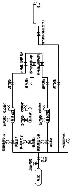
[0021] Such as figure 1 As shown, a high-pressure cleaning and oiling system includes a cleaning and oiling system. The cleaning and oiling system includes a parallel cleaning system, an air drying system, an injection system and an air pump pressure gauge. The left end of the cleaning and oiling system is connected in series with an air supply device, and the right end Tandem nozzles.

[0022] Preferably, a main air release valve and a main air outlet valve are sequentially connected in series between the air supply device and the cleaning and oil injection system.

[0023] Preferably, the cleaning system includes a pressure regulating valve 1, a cleaning liquid tank, a box air valve a and a gun air valve A connected in series from left to right, and the air-drying system includes a box air valve d connected in series from left to right and gun air valve D.

[0024] Preferably, the injection system includes an engine oil injection system and a lubricating oil injection syst...


PUM


Abstract

The invention provides a high-pressure cleaning oiling system. The high-pressure cleaning oiling system comprises a cleaning oiling system. The cleaning oiling system comprises a cleaning system, an air drying system, an injecting system and an air pump pressure gauge; the left end of the cleaning oiling system is connected with an air supplying device in series and the right end of the cleaning oiling system is connected with an injecting head in series; a main deflation valve and a main air outlet valve is sequentially connected between the air supplying device and the cleaning oiling systemin series. The invention further comprises a high-pressure cleaning oiling method of the high-pressure cleaning oiling system. The method mainly comprises steps of cleaning, air drying and oiling. The system is easy and convenient to operate, strong in controllability, good in cleaning effect, good in oiling effect and capable of realizing the complete coverage of lubricating oil.

Description

technical field [0001] The invention relates to an oil injection device, in particular to a high-pressure cleaning oil injection system and an oil injection method. Background technique [0002] According to statistics, 70% of the problems of jamming and refusal of the knife switch are caused by the failure of the lubrication of the rotating parts. The dry sludge formed by the old lubricating oil in the rotating part of the knife switch no longer has a lubricating effect, and the traditional maintenance process cannot completely clean the sludge in the gap of the shaft pin sleeve. Due to the limitation of the structure of the rotating parts, the lubricating oil applied from the outside cannot fully cover the shaft. If the contact surface of the pin is damaged, the shaft pin will be corroded, which will aggravate the jamming of the knife switch, and even refuse to move in severe cases. In addition, for the circuit breaker operating mechanism, due to the dense and compact lay...

Claims


Application Information

Patent Timeline
IPC IPC(8): B08B3/02F16N7/38F16N7/32F26B21/00
CPCF16N7/32F16N7/385F26B21/00B08B3/02
Inventor 何利平穆文革田志杰何勇亮穆昕宇王荷生马立平常剑锋穆存正王胜亮穆文联丛龙祥姚保全
Owner STATE GRID CORP OF CHINA
Learn More