
Multi-channel gasification bio-particle combustion engine and work method thereof

A biological particle and burner technology, which is used in combustion equipment, solid fuel combustion, lighting and heating equipment, etc., can solve the problems of low efficiency, inconvenience, and inability to clean the internal gasification chamber, and achieve good cleaning effect and improve The effect of processing efficiency

Inactive Publication Date: 2014-01-29
浙江和西东新能源科技有限公司
View PDF0 Cites 8 Cited by
  • Summary
  • Abstract
  • Description
  • Claims
  • Application Information

AI Technical Summary

Problems solved by technology

The traditional biomass pellet burner uses a gasification chamber. After the combustion raw material is fed from the feeding box, it directly enters the gasification chamber and starts to be processed. After one feeding, the gasification chamber is filled and the feeding box stops. operation, wait until the gasification chamber is in operation and then feed the combustion raw materials. This processing method is very inefficient; moreover, there is only one traditional gasification chamber, and all combustion raw materials are gasified and combusted in one gasification chamber. Let the combustion raw materials with a higher gasification combustion point be processed thoroughly, not only incomplete combustion but also a lot of residues
Although the biological pellet burner burns more thoroughly than many heating equipment, it is impossible to have no residue, so it needs to be cleaned after use. The traditional biological pellet burner only has an openable door on the outermost side. When the internal gasification chamber cannot be cleaned, it is very inconvenient

Method used


Image

  • Multi-channel gasification bio-particle combustion engine and work method thereof

Examples


Embodiment Construction

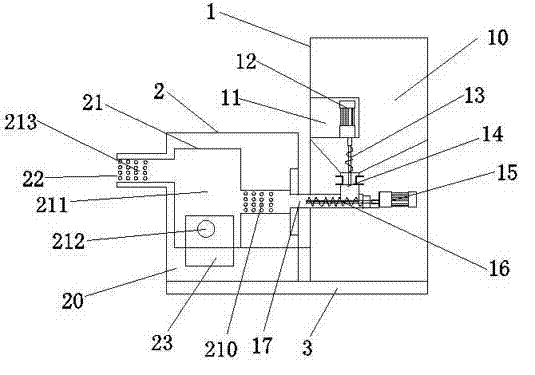
[0018] refer to figure 1 As shown, a multi-channel gasification biological particle burner includes a particle combustion box 2, a charging box 1 connected to the particle combustion box 2, and a base 3 arranged under the particle combustion box 2 and the charging box 1; The charging box 1 includes a storage hopper 10, a first motor protection case 11 disposed in the storage hopper 10, a first motor 12 disposed in the first motor protection case 11, and a first motor 12 connected at one end to the first motor 12. Screw rod 13, and the first feed pipe 14 that links to each other with storage hopper 10 ends, and the second motor 15 that is arranged on the first feed pipe 14 below, and the second screw rod 16 that one end links to each other with second motor 15, and one end connects with the second motor 15 A feed pipe 14 communicates with the second feed pipe 17; the particle combustion box 2 includes a combustion box outer chamber 20, and a combustion box inner chamber 21 arra...


PUM


Abstract

The invention discloses a multi-channel gasification bio-particle combustion engine which comprises a particle combustion box, a feeding box connected with the particle combustion box and a base on the lower portion of the particle combustion box and the lower portion of the feeding box. The feeding box comprises a material storage hopper, a first motor protection shell in the material storage hopper, a first motor in the first motor protection shell, a first screw rod connected with the first motor, a first feeding pipe connected with the tail end of the material storage hopper, a second motor below the first feeding pipe, a second screw rod connected with the second motor and a second feeding pipe communicated with the first feeding pipe. The particle combustion box comprises a combustion box outer chamber, a combustion box inner chamber inside the combustion box outer chamber, a combustion box openable door and a fire ejection opening, wherein the combustion box openable door and the fire ejection opening are in the combustion box outer chamber. The combustion box inner chamber comprises a first gasification chamber, a second gasification chamber, a combustion box inner chamber openable door and a third gasification chamber. The multi-channel gasification bio-particle combustion engine has the advantages of being complete in combustion, convenient to clean and high in efficiency.

Description

technical field [0001] The invention relates to a multi-channel gasification biological particle burner and its working method. Background technique [0002] The biomass pellet burner is a kind of heating equipment that uses plant waste (straw, wood chips, etc.) as the combustion medium. It can burn a large amount of waste and convert it into a usable medium. The traditional biomass pellet burner uses a gasification chamber. After the combustion raw material is fed into the gasification chamber from the feeding box, it directly enters the gasification chamber to be processed. After one feeding, the gasification chamber is filled and the feeding box stops. operation, wait until the gasification chamber is in operation and then feed the combustion raw materials. This processing method is very inefficient; moreover, there is only one traditional gasification chamber, and all combustion raw materials are gasified and combusted in one gasification chamber. Let the combustion...

Claims


Application Information

Patent Timeline
IPC IPC(8): F23B90/06
Inventor 田和东
Owner 浙江和西东新能源科技有限公司
Learn More