Heat conductivity tester

A thermal conductivity tester and heating module technology, applied in the direction of material thermal development, can solve problems such as difficult maintenance and complex structure, and achieve the effects of easy maintenance, simple structure, and easy removal.

Active Publication Date: 2014-01-29
SHENZHEN KAIFA TECH
View PDF8 Cites 17 Cited by
  • Summary
  • Abstract
  • Description
  • Claims
  • Application Information

AI Technical Summary

Problems solved by technology

[0005] The technical problem to be solved by the present invention is to provide a thermal conductivity tester with a simple structure and easy maintenance for the existing thermal conductivity tester with complex structure and difficult maintenance

Method used


Image

  • Heat conductivity tester
  • Heat conductivity tester

Examples


Embodiment Construction

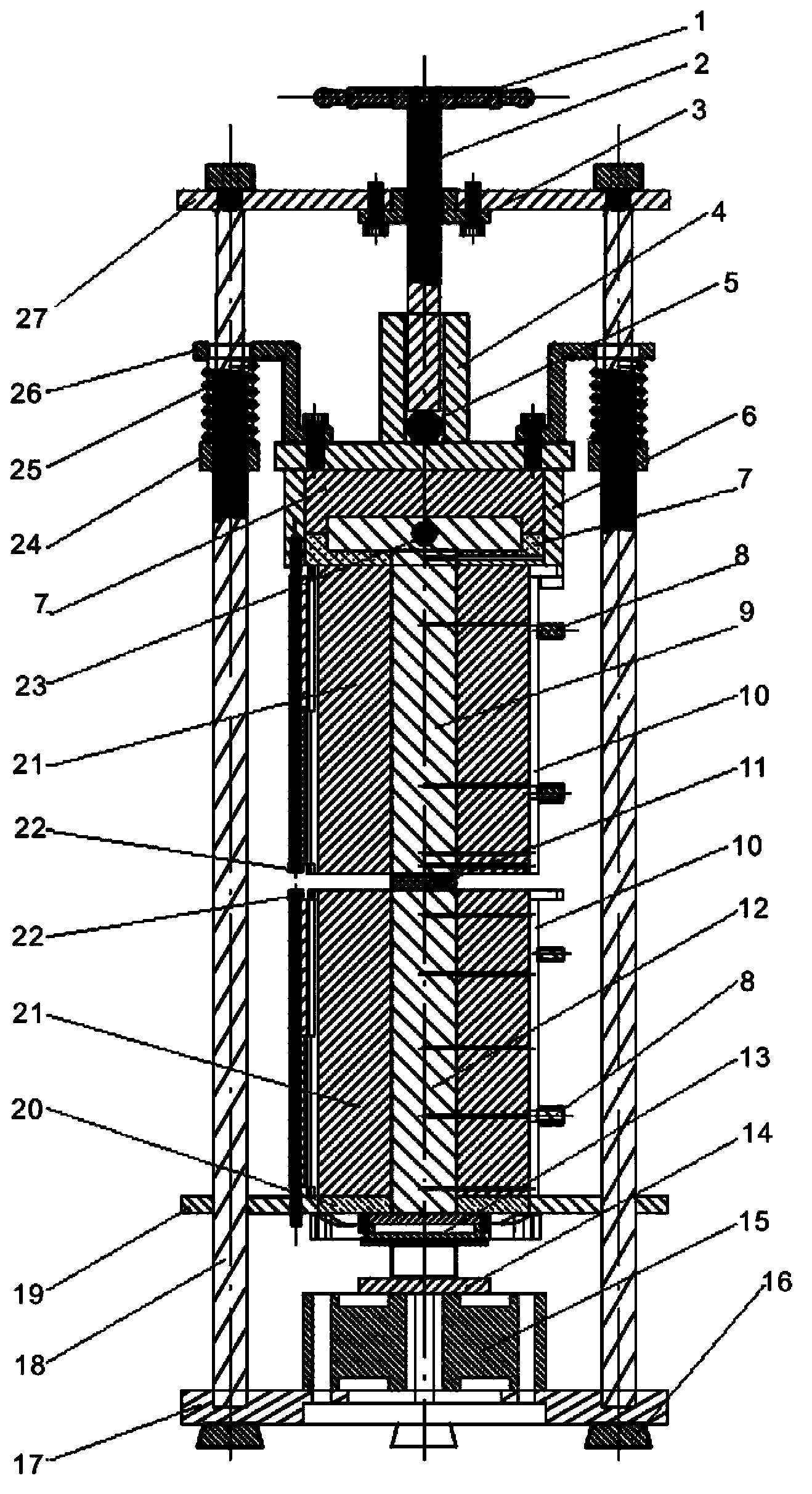
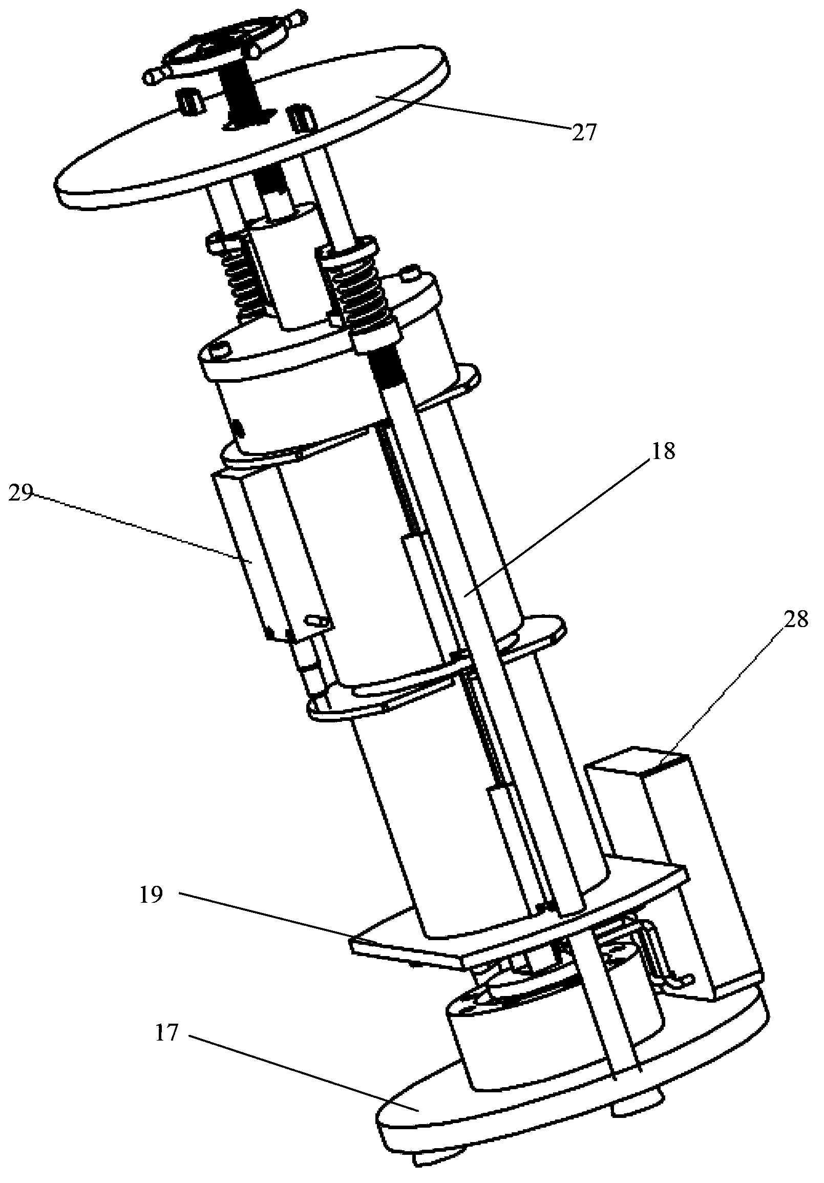
[0020] In order to have a clearer understanding of the technical features, purposes and effects of the present invention, the specific implementation manners of the present invention will now be described in detail with reference to the accompanying drawings.

[0021] Such as figure 1 , figure 2 As shown, a thermal conductivity tester of the present invention includes a frame, a heating module, a cooling module and a measuring module. The heating module is installed in the upper middle part of the rack, and the cooling module is installed in the lower middle part of the rack. The bottom surface of the heating module and the top surface of the cooling module form the upper and lower pressing surfaces of the sample 11 to be tested. The loading module is installed on the top of the rack and applies loading and pressure to the top surface of the heating module.

[0022] The measurement module includes thermocouples embedded in the heating module and the cooling module. Drill a...


PUM


Abstract

The invention relates to a heat conductivity tester which comprises a rack, a heating module, a cooling module and a measuring module, wherein the heating module is arranged at the upper-middle part of the rack, the cooling module is arranged at the lower-middle part of the rack, a loading module is arranged at the top of the rack and is used for loading and pressing the top surface of the heating module, the measuring module comprises thermocouples embedded in the heating module and the cooling module, the heating module and the cooling module are sheathed in heat insulation devices (21) which are locked and fixed through a fastening device (10), the fastening device (10) comprises two hooping members, one sides of the two hooping members are connected through a hinge, and the other sides of the two hooping members are detachably connected. The heat conductivity tester provided by the invention is simple in structure, convenient to install and easy to maintain.

Description

technical field [0001] The invention relates to the technical field of thermal physical property testing of materials, in particular to a thermal conductivity tester. Background technique [0002] With the extension of LEDs to emerging fields such as rear projection, street lights, and automotive lights, LED devices as light sources are also developing towards high power density, high brightness, and high integration. There are many problems such as luminosity reduction, wavelength shift, and shortened service life. Therefore, the heat dissipation of LEDs is particularly prominent. At present, heat dissipation has become one of the technical bottlenecks restricting these applications. [0003] LED substrate, chip bonding layer, and thermal interface thermal grease, as part or intermediate links of the heat dissipation path, play a connecting role in the heat dissipation of the entire system. Once the materials are not selected properly, it will cause heat dissipation proble...

Claims


Application Information

Patent Timeline
Patent Type & Authority Applications(China)
IPC IPC(8): G01N25/20
Inventor 杨俊逸李齐渊孟田力何彩英冉红锋高双红
Owner SHENZHEN KAIFA TECH
Why Eureka
Try Eureka