Camera lens jitter compensation system and camera lens jitter compensation method

A compensation system and compensation method technology, applied in the field of anti-shake, can solve the problems of high sensor sensitivity and high cost, and achieve the effect of reducing production cost and sensitivity requirements

Inactive Publication Date: 2014-01-29
HONG FU JIN PRECISION IND (SHENZHEN) CO LTD +1
View PDF5 Cites 7 Cited by
  • Summary
  • Abstract
  • Description
  • Claims
  • Application Information

AI Technical Summary

Problems solved by technology

The shake compensation system obtains the shake amount of the lens in real time through the sensor, and controls the drive module to drive the lens to move for real-time compensation; since the sensor needs to sense the shake of the lens in real time during the shake compensation process of the lens, the Higher sensitivity requirements of the sensor, resulting in higher cost of the entire lens shake compensation system

Method used


Image

  • Camera lens jitter compensation system and camera lens jitter compensation method
  • Camera lens jitter compensation system and camera lens jitter compensation method

Examples


Embodiment Construction

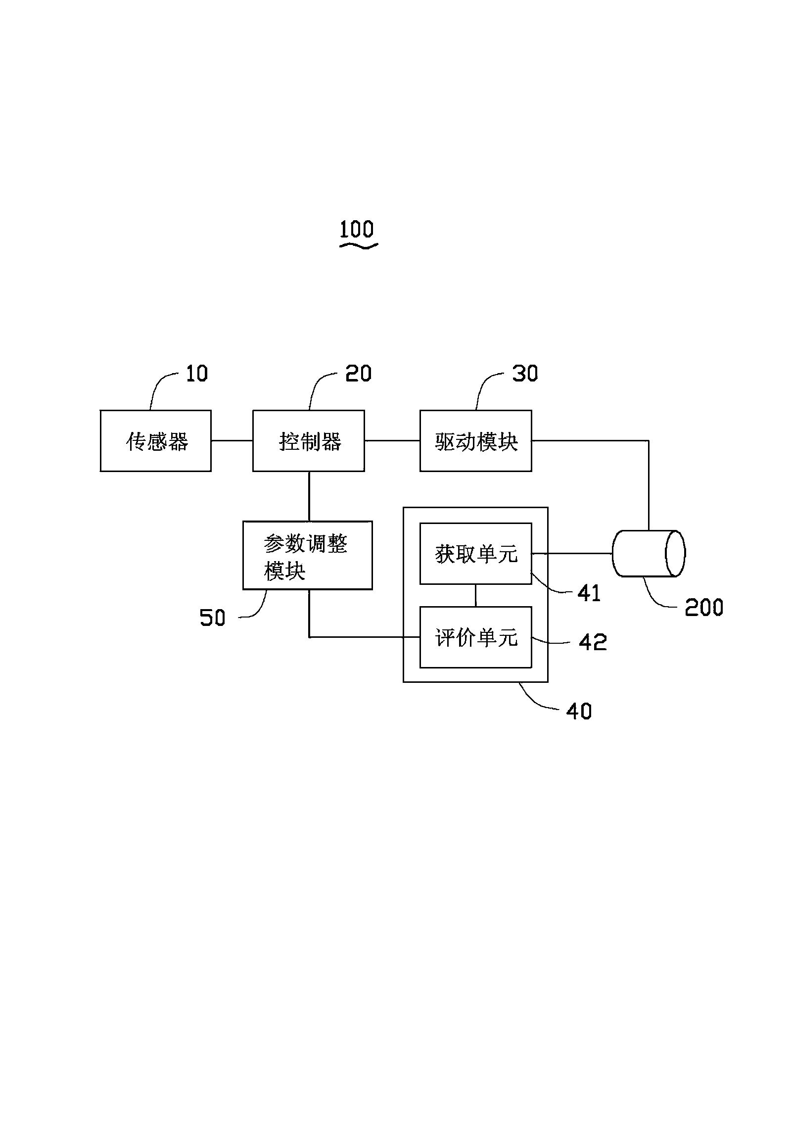
[0016] Such as figure 1 As shown, a lens shake compensation system 100 provided by an embodiment of the present invention is used for performing shake compensation on a lens 200 . The lens shake compensation system 100 includes a sensor 10 , a controller 20 , a driving module 30 , an image module 40 and a parameter adjustment module 50 .

[0017] The sensor 10 is used for sensing the shaking of the lens 200 . In this embodiment, the sensor 10 is a gyroscope. The sensor 10 and the lens 200 are respectively fixed in an electronic device (not shown) using the shake compensation system 100 , and the sensor 10 is relatively separated from the lens 200 . The sensor 10 is used for sensing the deflection of the electronic device while sensing the shake of the lens 200 to control the rotation of the screen of the electronic device.

[0018] The controller 20 is electrically connected to the sensor 10 , and outputs a shaking signal to the controller 20 when the sensor 10 senses the s...


PUM


Abstract

The invention provides a camera lens jitter compensation system which comprises a sensor, a controller, a driving module, an image module and a parameter adjusting module. A group of jitter compensation parameters is stored in the controller which has the jitter compensation parameters adjusted within a certain deviation range. The controller is used for controlling the driving module to drive a camera lens to move to perform jitter compensation according to the jitter compensation parameters after jittering of the camera lens is sensed by the sensor. The image module acquires images subjected to jitter compensation through the camera lens and analyzes resolution of the acquired images. The parameter adjusting module is used for adjusting the jitter compensation parameters when the resolution of the images is lower than a preset value so as to acquire the images with the resolution higher than the preset value. Since the jitter compensation parameters are judged whether or not to be in need of adjustment through evaluation of the resolution of the images after jitter compensation, requirements on sensitivity of the sensor are lowered.

Description

technical field [0001] The invention relates to an anti-shake technology, in particular to a lens shake compensation system and method. Background technique [0002] A conventional lens shake compensation system generally includes a sensor fixed with a lens and a driving module for driving the lens to move for shake compensation. The shake compensation system obtains the shake amount of the lens in real time through the sensor, and controls the drive module to drive the lens to move for real-time compensation; since the sensor needs to sense the shake of the lens in real time during the shake compensation process of the lens, the The sensitivity of the sensor is required to be high, resulting in a high cost of the entire lens shake compensation system. Contents of the invention [0003] In view of this, it is necessary to provide a cost-reduced lens shake compensation system and method. [0004] A lens shake compensation system is used for shake compensation of a lens. ...

Claims


Application Information

Patent Timeline
Patent Type & Authority Applications(China)
IPC IPC(8): G03B5/00H04N5/232
Inventor 陈昱翰梁禾凯
Owner HONG FU JIN PRECISION IND (SHENZHEN) CO LTD
Why Eureka
Try Eureka