Nondestructive testing method of hot grid scanning thermal imaging

A technology of non-destructive testing and scanning heat, which is applied in the direction of material defect testing, etc., can solve the problem that the sampling frequency or signal sensitivity cannot effectively detect cracks in the vertical direction, and achieve the requirements of reducing the sampling frequency and signal sensitivity, low signal sensitivity, and high sampling efficiency. The effect of low frequency

Active Publication Date: 2019-07-23
XI AN JIAOTONG UNIV
View PDF4 Cites 2 Cited by
  • Summary
  • Abstract
  • Description
  • Claims
  • Application Information

AI Technical Summary

Problems solved by technology

[0006] In view of the deficiencies in the prior art, the purpose of the present invention is to provide a thermal grid scanning thermal imaging non-destructive testing method and its application, which overcomes the extremely high sampling frequency or signal sensitivity of the thermal imager in the existing thermal wave detection method. Requirements for flaws and the problem that cracks in the vertical direction cannot be effectively detected

Method used


Image

  • Nondestructive testing method of hot grid scanning thermal imaging
  • Nondestructive testing method of hot grid scanning thermal imaging
  • Nondestructive testing method of hot grid scanning thermal imaging

Examples


Embodiment 1

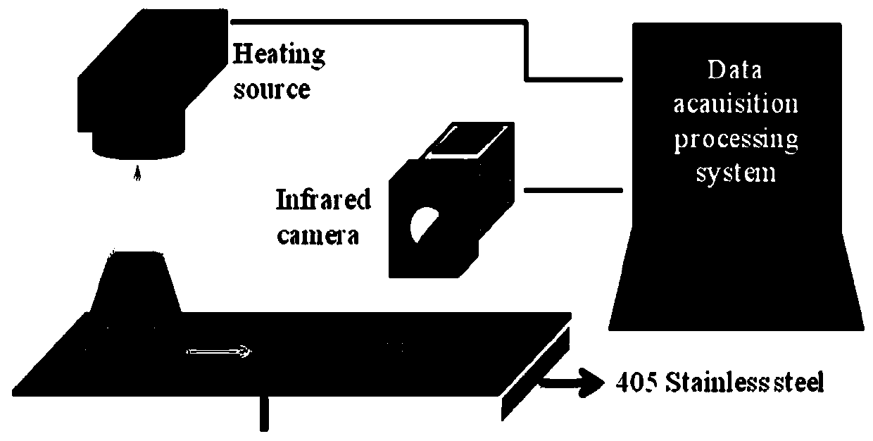
[0034] Comply with the above technical solutions, such as figure 1 As shown, this embodiment provides a thermal grid scanning thermal imaging non-destructive testing method, and the steps of this testing method are as follows:

[0035] Example 1 can detect vertical cracks in the ceramic thin film.

[0036]The detection frequency is 0.02Hz, the thermal grid wavelength is 40cm, the sample size is 40cm×4cm×1cm, and the surface is sprayed with yttria-stabilized zirconia (8wt.% YSZ) with APS to prepare a TBC coating with a thickness of 200μm.

[0037] In order to facilitate the understanding of the implementation of the invention, specific application descriptions are given below for the implementation of the invention.

[0038] (1) The moving grating image is generated by computer software, and the projector is used to project on the surface of the film. In order to enhance the thermal wave signal, it is better to use a traditional thermal light source projector instead of LED li...

Embodiment 2

[0043] According to the above technical scheme, using MATLAB for numerical simulation analysis, this embodiment provides a thermal grid scanning thermal imaging non-destructive testing method, the steps of this testing method are as follows:

[0044] Example 2 can detect horizontal cracks in the ceramic thin film.

[0045] The detection frequency is 0.02Hz, the thermal grid wavelength is 40cm, the specimen size is 1cm×0.3cm×0.1cm, the material is 405 stainless steel, the horizontal crack length is 0.06cm, and the depth is 0.02cm.

[0046] In order to facilitate the understanding of the implementation of the invention, the implementation of this patent is given below with specific application instructions.

[0047] (1) The heat source loading form is 100*sin(0.02π*t+0.5*x), the initial temperature is 0, and the boundary conditions are adiabatic boundary conditions on all surfaces except the heating surface;

[0048] (2) Write the heat conduction calculation program by yourself...


PUM


Abstract

The invention discloses a nondestructive testing method of hot grid scanning thermal imaging. A temperature signal of a steady heat wave formed by a grid heat source on the surface of a thin film is recorded by a thermal imager, and horizontal and vertical cracks in the thin film are detected. According to the testing method, the requirements for the sampling frequency and the signal sensitivity of the thermal imager are lowered, the surface of the thin film is rarely disturbed by various defects such as the surface color and surface element distribution, the requirement for the sensitivity ofthe thermal imager signal is low, and the nondestructive testing method is especially suitable for thin films capable of withstanding the high temperature.

Description

technical field [0001] The invention belongs to the technical field of infrared nondestructive testing, and in particular relates to a thermal grid scanning thermal imaging nondestructive testing method suitable for thin films. Background technique [0002] Thin film structure is widely used in industry, scientific research, life and other aspects, and it is a very important basic structure. In the semiconductor industry, for example, chips contain a large number of membrane structures; display screens are mainly thin-film structures, and the concept of flexible electronics that is rapidly developing today is also mainly composed of flexible thin films; key components such as aeroengines and gas turbine high-temperature blades are protected by thermal barrier coatings. Thermal protection, in addition to various environmental barrier coatings are typical thin film structures. There are various permeable membrane structures for air purification and water purification in life....

Claims


Application Information

Patent Timeline
Patent Type & Authority Applications(China)
IPC IPC(8): G01N25/72
CPCG01N25/72
Inventor 张伟旭曲直张家宬
Owner XI AN JIAOTONG UNIV
Why Eureka
Try Eureka