
Trigger device for monitoring dropping process of tiny droplets

A technology of triggering device and tiny droplets, applied in analytical materials, instruments, etc., can solve the problems of high price, inability to accurately monitor the falling process of tiny droplets, low utilization rate of experimental space, etc., so as to reduce the use area and widen the monitoring Scope, the effect of reducing the space occupied

Inactive Publication Date: 2019-05-14
NORTHWESTERN POLYTECHNICAL UNIV +1
View PDF8 Cites 2 Cited by
  • Summary
  • Abstract
  • Description
  • Claims
  • Application Information

AI Technical Summary

Problems solved by technology

[0006] It is precisely because of the defects and deficiencies in the current trigger device for monitoring the falling process of tiny droplets (cannot accurately monitor the falling process of tiny droplets, high price, low utilization rate of experimental space, etc.), so it is necessary to develop a new A trigger device capable of monitoring the droplet drop process to meet the needs of more accurate, economical and rapid monitoring of the droplet drop process

Method used


Image

  • Trigger device for monitoring dropping process of tiny droplets

Examples


Embodiment Construction

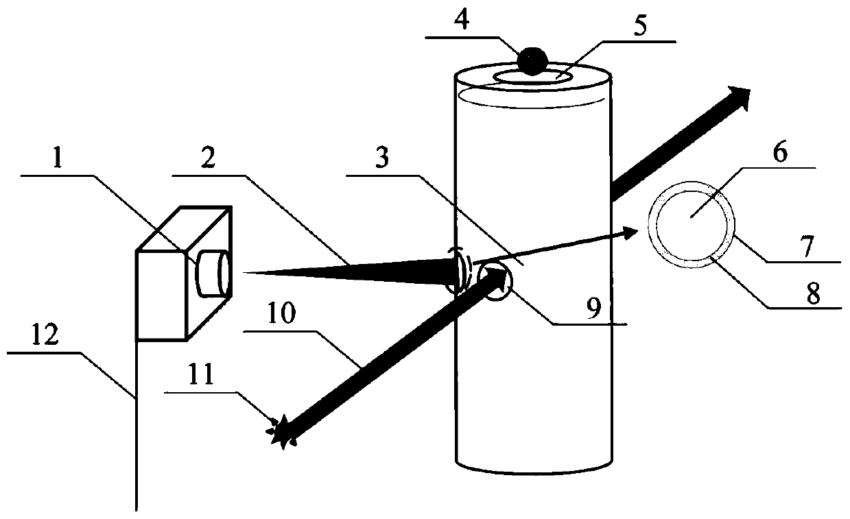
[0020] see figure 1 , the trigger device for monitoring the falling process of tiny droplets is characterized in that it consists of a photoelectric receiving device, a converging optical path, a connector, a droplet, a drop channel, a converging lens, a lens mounting cavity, an annular gasket, Optical path channel, cylindrical optical path, light source, trigger line; optical path generating system is mainly composed of light source, cylindrical optical path, optical path channel, mainly used to provide experimental parallel optical path; optical path receiving system is mainly composed of photoelectric receiving device, converging optical path, converging lens When the liquid drop passes through the cylindrical light path, the light reflected on the surface of the liquid drop is collected into the photoelectric receiving device through the converging lens, and the generated trigger signal is connected to the external device through the trigger line to control the progress of ...


PUM

PropertyMeasurementUnit
Diameteraaaaaaaaaa
Diameteraaaaaaaaaa

Abstract

The invention discloses a trigger device for monitoring dropping process of tiny droplets. The trigger device is composed of a photoelectric receiving device, a convergent light path, connecting pieces, droplets, a drop channel, a convergent lens, a lens mounting cavity, an annular gasket, a light path channel, a cylindrical light path, a light source and a trigger line; the trigger device uses the principle of light reflection (droplets are reflected when passing through a parallel light path), and the lens is additionally added to converge the reflected light to monitor the dropping processof the tiny droplets (a droplet diameter is between 0.1 mm and 3 mm). Compared with a traditional trigger device, the monitoring range of the trigger device is widened, the accuracy of measurement results (convergence effects of trigger signals) is improved, the experimental cost (the sensitivity requirement of a photoelectric sensor is reduced) is reduced, and meanwhile, the space utilization rate of the experimental system (the same side arrangement of experimental equipment is adopted) is improved, and the dropping process of the droplets can be monitored more quickly, economically and accurately.

Description

technical field [0001] The invention relates to the field of hypersonic vehicle combustion, in particular to a trigger device for monitoring the drop process of tiny liquid droplets. Background technique [0002] Since the beginning of the 21st century, all major military powers in the world have regarded the development of hypersonic vehicles as the top priority of their national defense undertakings, and their development is of great significance to safeguarding national security and improving overall strength. In addition, during the development of hypersonic vehicles, it is possible to promote a new round of technological revolution. [0003] As the flight Mach number of hypersonic vehicles increases, researchers' requirements for aircraft propulsion devices are also increasing. Combustion chamber, as the place where fuel chemical energy is released in the propulsion system, provides energy supply for the normal operation of the propulsion device and aircraft, and plays...

Claims


Application Information

Patent Timeline
IPC IPC(8): G01N15/00
Inventor 李建玲申帅刘金宏范玮董荣晓张晋
Owner NORTHWESTERN POLYTECHNICAL UNIV
Learn More