Double-mercury lamp spliced exposure system for lithography equipment

An exposure system and lithography equipment technology, which is applied in the field of double mercury lamp splicing exposure system, can solve the problems of difficult control and low lighting precision, and achieve the effect of improving illuminance

Active Publication Date: 2014-01-29
SHANGHAI MICRO ELECTRONICS EQUIP (GRP) CO LTD
View PDF5 Cites 13 Cited by
  • Summary
  • Abstract
  • Description
  • Claims
  • Application Information

AI Technical Summary

Problems solved by technology

[0006] In view of this, there is a need for a new dual-light source lighting technology in the prior art, which can effectively overcome the shortcomings of low lighting accuracy and difficult control in the prior art.

Method used


Image

  • Double-mercury lamp spliced exposure system for lithography equipment
  • Double-mercury lamp spliced exposure system for lithography equipment
  • Double-mercury lamp spliced exposure system for lithography equipment

Examples


Embodiment Construction

[0019] Specific embodiments of the present invention will be described in detail below in conjunction with the accompanying drawings.

[0020] The present invention expects to provide an optical system for splicing double mercury lamps, which can accurately monitor and control the energy of the double light sources while increasing the illuminance on the substrate, and can realize switching between the working modes of the double lamps and single lamp.

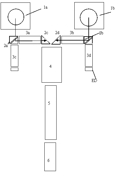
[0021] figure 1 It is a schematic diagram of the overall structure of the double mercury lamp splicing exposure system involved in the present invention. like figure 1 As shown in , the double mercury lamp splicing exposure system is mainly composed of the following modules: light source 1, rectangular prism 2, small quartz rod 3, coupling lens group 4, large quartz rod 5, and relay lens group 6. Here, the small quartz rod 3 and the large quartz rod 5 are defined according to the relative size of their volumes. like figure...


PUM


Abstract

The invention discloses a double-mercury lamp spliced exposure system for lithography equipment. The double-mercury lamp spliced exposure system comprises a first light source and a second light source used for simultaneously or respectively providing illuminating beams; a first dodging component and a second dodging component which respectively correspond to the first light source and the second light source, a coupling lens group used for improving the illumination uniformity of the exposure system, and an illuminating and dodging component used for dodging emergent light of the coupling lens group to illuminate an illumination surface.

Description

technical field [0001] The invention relates to the field of integrated circuit equipment manufacturing, in particular to a double mercury lamp splicing exposure system for photolithography equipment. Background technique [0002] The photolithography device is the main equipment for manufacturing integrated circuits. Its function is to sequentially image different mask patterns onto the precisely aligned positions on the substrate (such as semiconductor silicon wafer or LCD panel). However, this alignment position changes due to the physical and chemical changes experienced by successive patterns, so an alignment system is needed to ensure that the alignment position of the silicon wafer corresponding to the mask can be accurately aligned every time. As the number of electronic components per unit surface area of ​​the substrate increases and the size of electronic components becomes smaller and smaller, the precision requirements for integrated circuits are increasing. The...

Claims


Application Information

Patent Timeline
Patent Type & Authority Applications(China)
IPC IPC(8): G03F7/20G02B27/09
Inventor 陈璐玲张祥翔
Owner SHANGHAI MICRO ELECTRONICS EQUIP (GRP) CO LTD
Why Eureka
Try Eureka