Magnetic shoe structure of direct-current micromotor

A micro-motor and magnetic tile technology, applied in the shape/style/structure of the magnetic circuit, static components of the magnetic circuit, etc., can solve the problems of difficult to meet environmental protection requirements, low load speed, large load current, etc., and achieve small current rise, The effect of reducing the influence of magnetic field and good product performance

Active Publication Date: 2014-01-29
自贡市江阳磁材有限责任公司
View PDF6 Cites 0 Cited by
  • Summary
  • Abstract
  • Description
  • Claims
  • Application Information

AI Technical Summary

Problems solved by technology

The former one has higher noise and lower load speed
The latter type has lower noise, but the load speed still does not meet the high-end requirements, and the load current will be too large, which makes it difficult to meet higher environmental protection requirements

Method used


Image

  • Magnetic shoe structure of direct-current micromotor
  • Magnetic shoe structure of direct-current micromotor
  • Magnetic shoe structure of direct-current micromotor

Examples


Embodiment Construction

[0020] The present invention will be described in further detail below in conjunction with the accompanying drawings and specific embodiments.

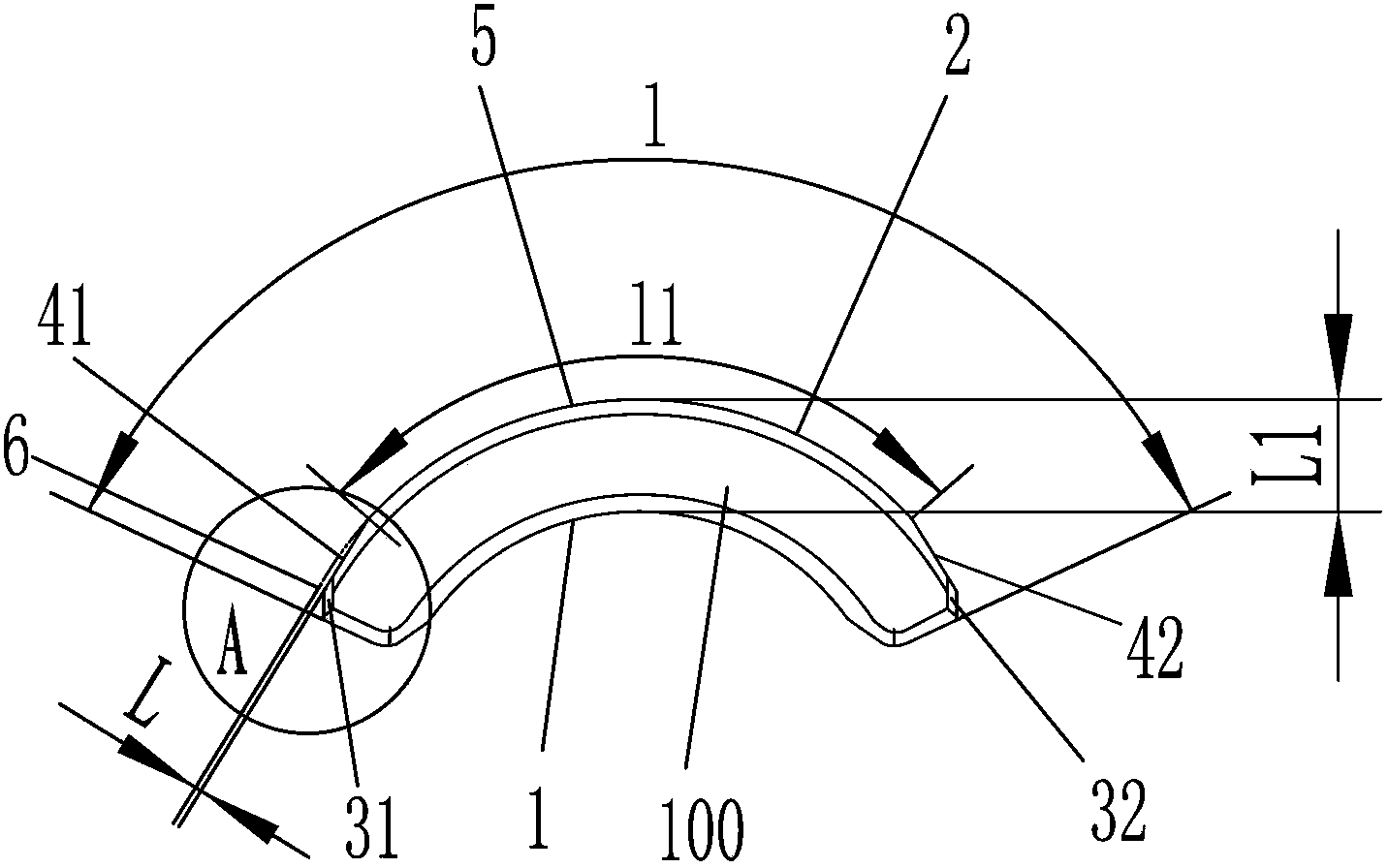
[0021] Such as Figure 3 to Figure 6 The magnetic tile structure of a DC micro-motor shown in , includes a magnetic tile body 100, the inner arc surface 1 and the outer arc surface 2 of the magnetic tile body 100 are concentric, and the two ends of the outer arc surface 2 respectively have an R angle 31 , 32, respectively along the inner ends of the two R angles facing inwardly, a flat cut surface 41, 42 is provided on the outer arc surface, and the two flat cut surfaces 41, 42 are symmetrical to each other. There is a distance between the tangent surfaces 41, 42 and the extension surface 6 of the arc surface 5 in the middle of the outer arc surface, wherein the vertical distance L between the outer end point of the tangent surface and the extension surface 6 is the distance between the outer arc surface 2 and the extension surface 6....


PUM


Abstract

A magnetic shoe structure of a direct-current micromotor comprises a magnetic shoe body, wherein an inner cambered surface and an outer cambered surface of the magnetic shoe body are concentric; and two R corners are respectively arranged at two ends of the outer cambered surface. The magnetic shoe structure of the direct-current micromotor is characterized in that two flat sections are oppositely arranged on the outer cambered surface inwards along the inner ends of the two R corners, and are symmetrical to each other; and a gap is formed between each flat section and an lengthened surface of an arc-shaped surface in the middle of the outer cambered surface. The vertical distance L between the outer end of each flat section and the arc-shaped lengthened surface of the outer cambered surface is 7%-8% of a distance L1 between the outer cambered surface and the inner cambered surface. The arc length l1 of the arc-shaped surface in the middle of the outer cambered surface is 75%-78% of the whole arc length of the outer cambered surface. By the magnetic shoe structure, the increasing degree of current of the micromotor is reduced under the condition that the load speed of the micromotor is greatly increased, and moreover, noise can be reduced.

Description

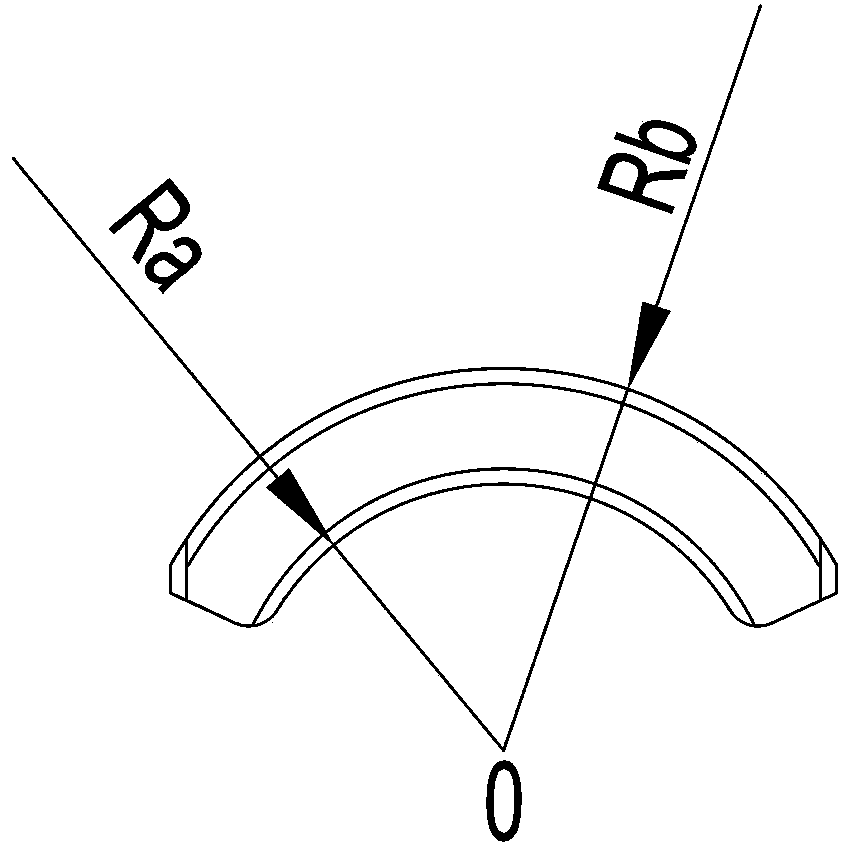
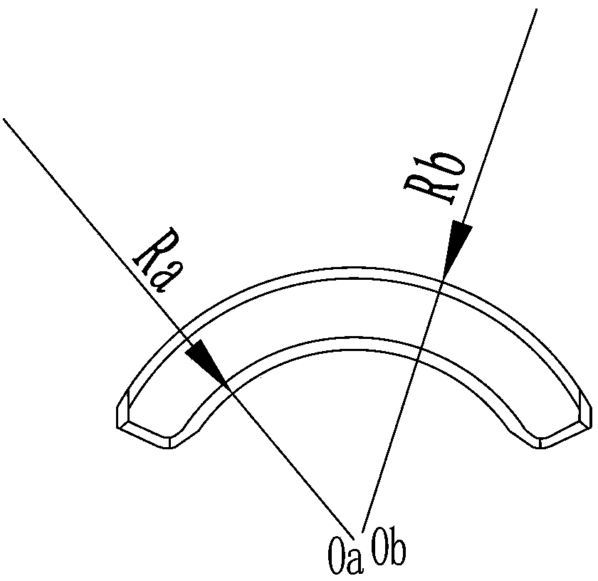
technical field [0001] The invention relates to a magnetic tile structure of a motor, in particular to a magnetic tile structure of a DC micro-motor. Background technique [0002] The magnetic tile structure used as the stator of the existing DC micro-motor is the following two structures: 1) the concentric magnetic tile, the inner arc Ra and the outer arc surface Rb all take O as the center of the circle, that is, the wall thickness is equal thickness, so The air gap between the rotor and the stator of the micromotor is as large as figure 1 shown in . 2) For eccentric magnetic tiles, the inner arc Ra and the outer arc surface Rb are centered at Oa and Ob points respectively, that is, the wall thickness is the thickest in the middle and slightly thinner at both ends, such as figure 2 shown in . The former one has higher noise and lower load speed. The latter type has lower noise, but the load speed still does not meet the high-end requirements, and the load current will...

Claims


Application Information

Patent Timeline
Patent Type & Authority Applications(China)
IPC IPC(8): H02K1/12
Inventor 邓志刚袁昱
Owner 自贡市江阳磁材有限责任公司
Why Eureka
Try Eureka