
Built-in precise centering device of gyroscope

A centering device and gyroscope technology, applied in gyroscope/steering sensing equipment, measuring device, gyro effect for speed measurement, etc., can solve the problems of large differences in assembly status, hidden dangers of misoperation, and the inability of special-purpose test equipment, etc. problems, to avoid rigid contact and wear, and reduce magnetic field interference

Pending Publication Date: 2021-12-31
西安立中测控科技有限公司
View PDF0 Cites 0 Cited by
  • Summary
  • Abstract
  • Description
  • Claims
  • Application Information

AI Technical Summary

Problems solved by technology

[0003] At present, the assembly process of magnetic suspension bearings relies solely on the size of the machine, and the assembly position of the floater is manually judged. The test equipment cannot be dedicated, and the operation and detection process is cumbersome. Large contrast

Method used


Image

  • Built-in precise centering device of gyroscope
  • Built-in precise centering device of gyroscope
  • Built-in precise centering device of gyroscope

Examples


Embodiment Construction

[0029] The object of the present invention can be achieved by the following technical solutions:

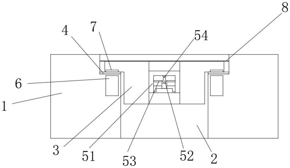
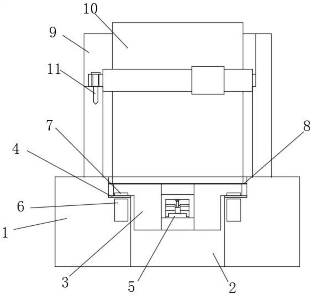
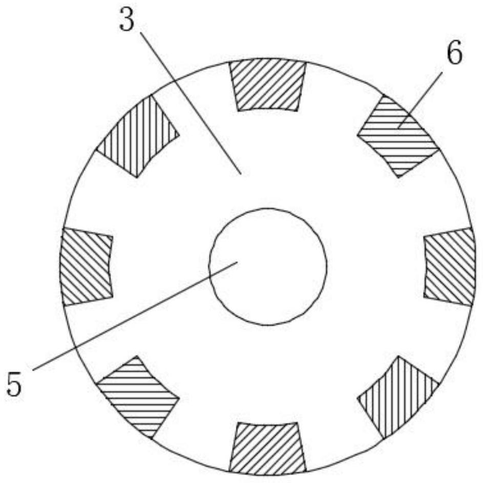
[0030] A gyroscope's built-in precision pair, see Figure 1 ~ 3 , Including housing 1, through holes 2, suspension 3, cushion 4, gem bearings 5, electromagnet 6, magnet 7, magnetic shield 8;

[0031] The housing 1 is provided with a through hole 2, and a suspension 3 is provided in the through hole 2, and the through hole 2, and the suspension 3 are disposed between the suspension 4; the cushion 4 pairs of suspensions 3, the housing 1 The rigid contact is to the buffer, avoiding the suspension 3 to generate a variation on the housing 1, affecting the center of gravity distribution of the suspension 3;

[0032] A gem bearing 5 is mounted in the suspension 3;

[0033] An magnet 7 is provided in the suspension 3, and the magnet 7 is mounted in the outer bump of the tip of the suspension 3;

[0034] An electromagnet 6 is provided in the housing 1, and the electromagnet 6 is mounted within...


PUM


Abstract

The invention discloses a built-in precise centering device of a gyroscope. The built-in precise centering device comprises a shell, a through hole, a suspension body, a buffer pad, a jewel bearing, an electromagnet, a magnet and a magnetic shielding cover; The through hole is formed in the center of the shell, the suspension body is installed in the through hole, and the buffer pad is arranged between the through hole and the suspension body. The jewel bearing is mounted in the suspension body; the magnet is arranged in the suspension body and is mounted on the lower surface of a bulge on the outer side of the top end of the suspension body; the electromagnet is arranged in the shell, the electromagnet is arranged in the shell below the external expansion groove at the top end of the through hole, the electromagnet is opposite to the magnet on the suspension body, and the magnet is matched with the electromagnet. The built-in precise centering device has the characteristics that rigid contact and abrasion are avoided, the centering control circuit detects and adjusts magnetic suspension centering, and magnetic field interference on the gyroscope is reduced.

Description

Technical field [0001] The present invention relates to a gyroscope's built-in precision pair device, in particular, has a built-in precision of a gyroscope that avoids rigid contact and wear, a pair control circuit to magnetic suspension pair, reducing the gyroscope Middleware. Background technique [0002] The three floats are a new gyroscope integrating liquid float, dynamic air floating, magnetic suspension, which is mainly composed of float assemblies, torque holder assemblies, sensor seat assemblies, left and right end caps, magnetic suspension bearings, and the like. Among them, the magnetic suspension element geometry center, force center, and signal center non-coefficient is an important factor that causes the accuracy error of the meter, and is also the main reason for the magnetic suspension interference moment, so the magnetic suspension bearing requires high pairs of assembly accuracy. [0003] At present, the magnetic suspension bearing assembly process is simply de...

Claims


Application Information

Patent Timeline
Patent Type & Authority Applications(China)
IPC IPC(8): G01C19/00G01C15/08
CPCG01C19/00G01C15/08
Inventor 高立亭孟娜高天
Owner 西安立中测控科技有限公司
Learn More